Electric power converter apparatus which attenuates frequency components of ripple in output current

a technology of ripple current and power converter, which is applied in the direction of power conversion systems, dc-dc conversion, instruments, etc., can solve the problems of substantial electrical noise produced by output current and interference with radio reception, and achieve the effect of reducing interference and reducing ripple current frequency components

Active Publication Date: 2015-12-24
DENSO CORP
View PDF6 Cites 6 Cited by
  • Summary
  • Abstract
  • Description
  • Claims
  • Application Information

AI Technical Summary

Benefits of technology

[0017]In that way, the amplitude of the ripple current frequency components can be achieved effectively, by selecting the most appropriate data map in accordance with the respective frequencies and amplitudes of the ripple current frequency components that are presently contained in the output current from the electric power converter apparatus.
[0018]The control circuit may include both a frequency component analyzer section and also a data map correction section. The data map correction section serves to correct the respective phase difference values held in a data map, based on the analysis results from the frequency component analyzer section. For example, when a duty ratio has become set for the PWM signals, processing may be executed by the data map correction section for replacing the corresponding phase difference value (the value currently held in the data map) by a corrected phase difference value, which will more effectively reduce the amplitude of the ripple current frequency components.
[0019]The invention is particularly applicable to an electric power converter apparatus for installation in a motor vehicle, since the invention enables a reduction of interference with reception by a radio receiver of the vehicle, when the interference is caused by electrical noise produced by operation of the electric power converter apparatus.

Problems solved by technology

As a result, substantial electrical noise may be produced by the output current from such an electric power converter apparatus, at frequencies which are sufficiently high to cause interference with radio reception.

Method used


Image

  • Electric power converter apparatus which attenuates frequency components of ripple in output current
  • Electric power converter apparatus which attenuates frequency components of ripple in output current
  • Electric power converter apparatus which attenuates frequency components of ripple in output current

Examples


first embodiment

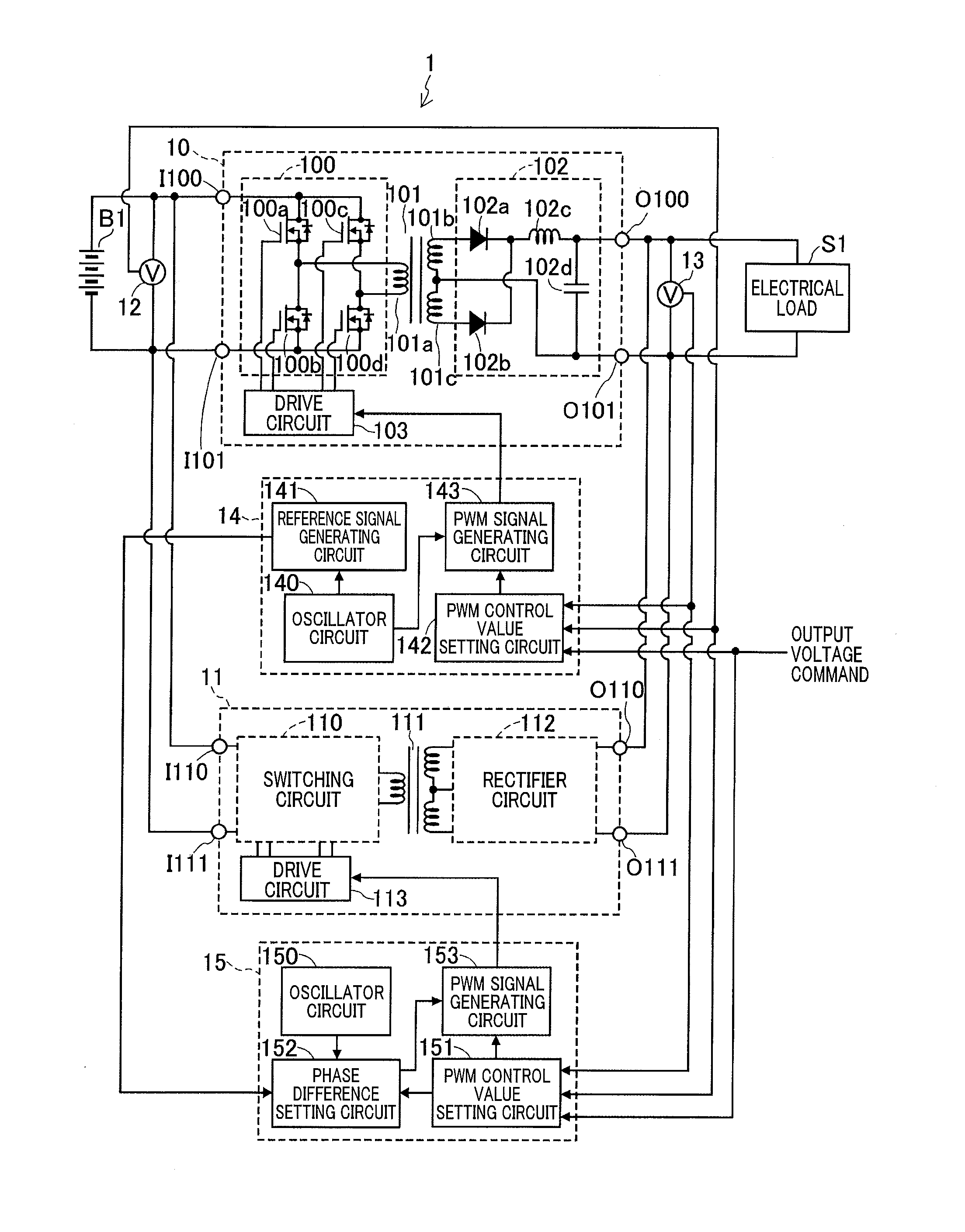
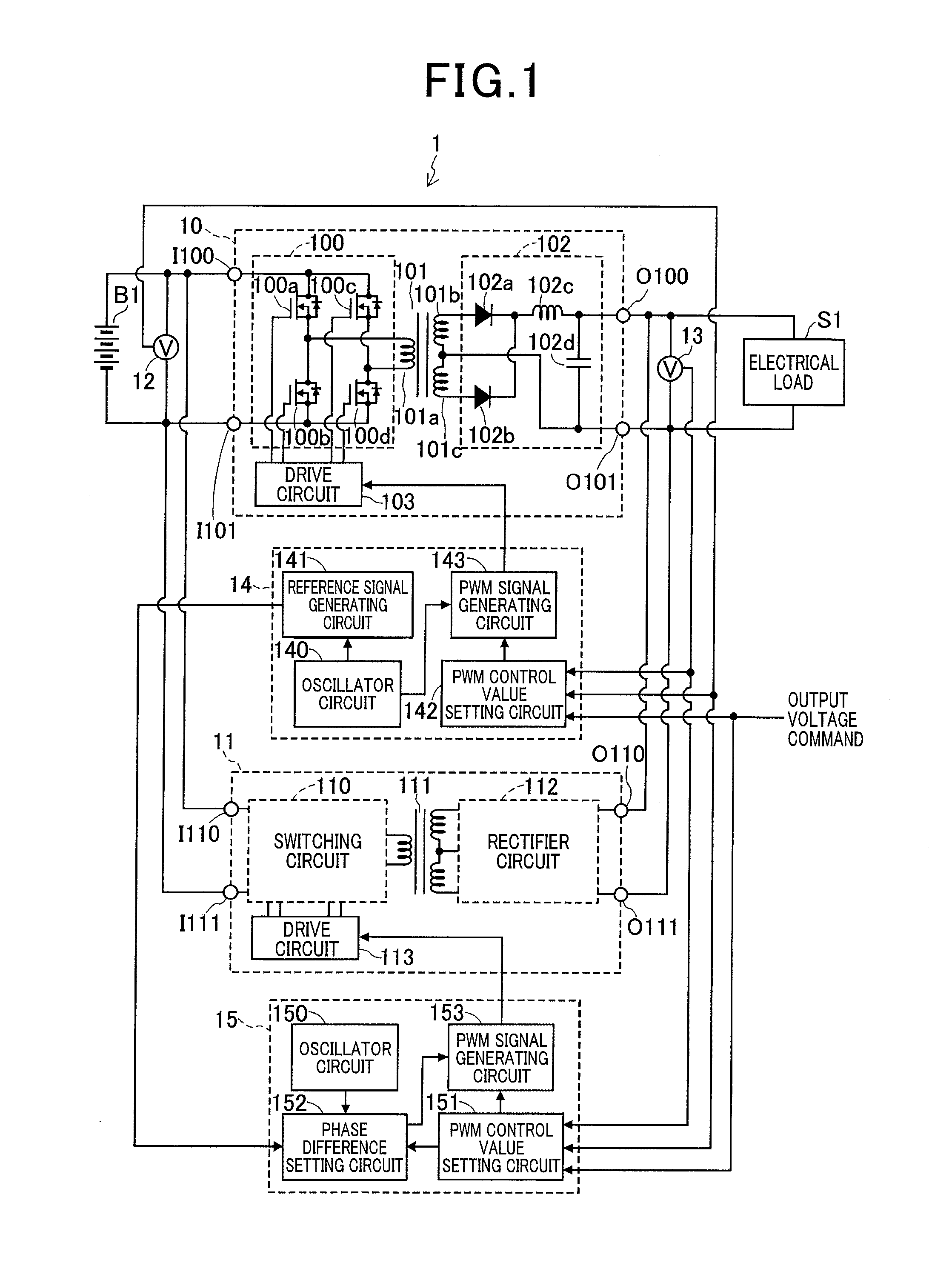
[0035]A first embodiment will be described referring to FIG. 1. As shown, an electric power converter apparatus 1 of this embodiment receives DC power from a high-voltage battery B1 of a vehicle, and converts this to output DC power which is supplied to an electrical load S1 of the vehicle. The electric power converter apparatus 1 includes two electric power converter circuits 10 and 11, voltage sensors 12 and 13, and two control circuits 13 and 14.

[0036]The electric power converter circuit 10 converts the input DC power, supplied from the high-voltage battery B1, to output DC power that is supplied to the electrical load S1, at a different voltage from that of the input DC power, with the output DC power electrically insulated from the input DC power. As shown, the electric power converter circuit 10 includes a switching circuit 100, a transformer 101, a rectifier circuit 102 and a drive circuit 103.

[0037]The switching circuit 100 converts the DC power from the high-voltage battery...

second embodiment

[0083]A second embodiment of an electric power converter apparatus is described in the following. This embodiment utilizes a data map as for the first embodiment, but differs from the first embodiment in that the phase difference values stored in the data map can be corrected during operation of the apparatus, as described in the following.

[0084]The electric power converter apparatus 2 of the second embodiment will be described referring to FIGS. 9 and 10. As shown in FIG. 9, the overall configuration is similar to the electric power converter apparatus 1 of the first embodiment, with DC power from a high-voltage battery B2 of a vehicle being converted to an DC power at a different voltage, and supplied to an electrical load S2 of the vehicle.

[0085]Electric power converter circuits 20 and 21 of this embodiment are identical to the circuits 10 and 11 respectively of the first embodiment. The voltage sensors 22 and 23 of the second embodiment are of identical type to the sensors 12 an...

third embodiment

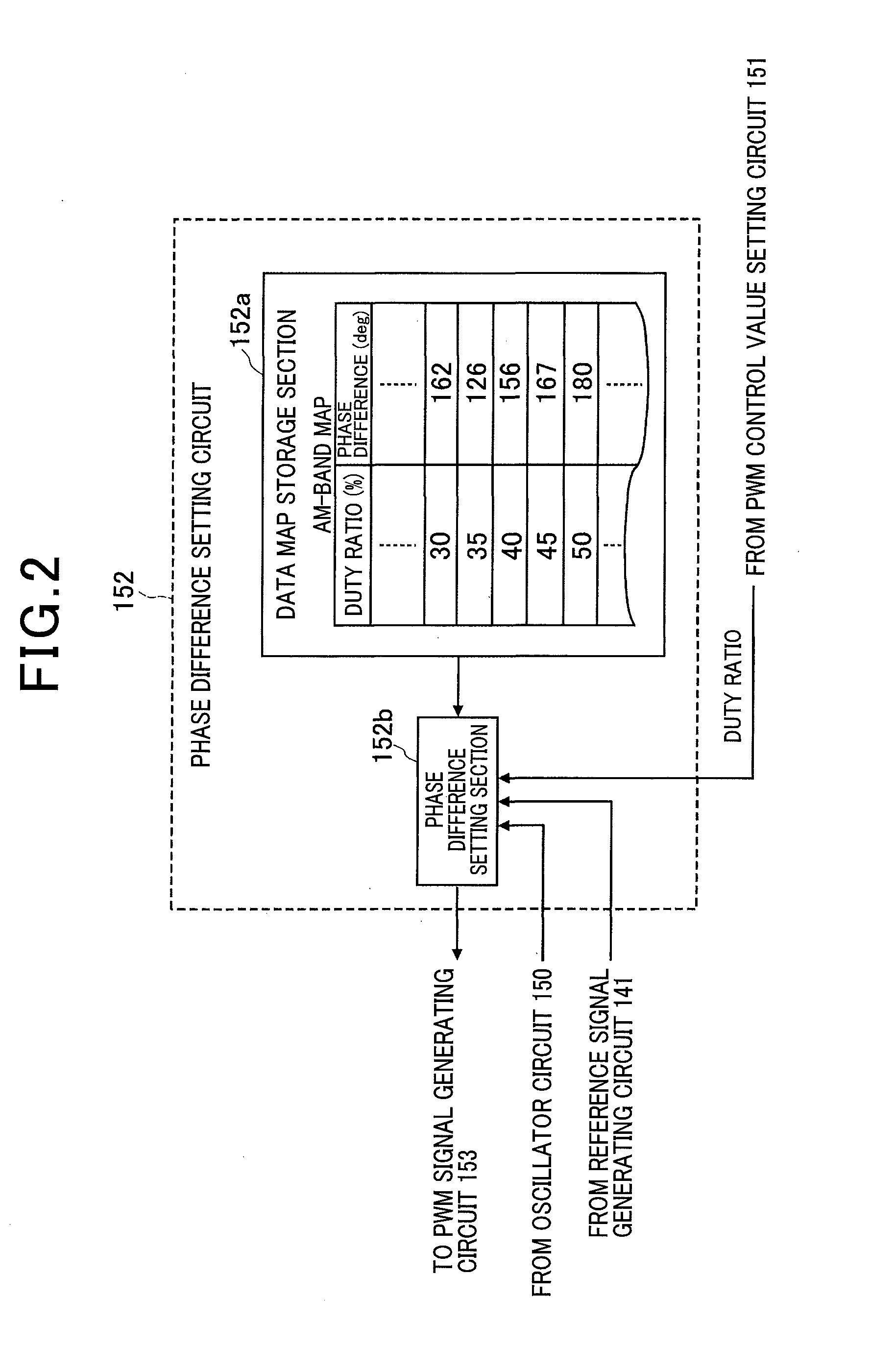
[0099]A third embodiment is described in the following. The electric power converter apparatus 3 of this embodiment utilizes a pair of data maps, respectively corresponding to AM-band and FM-band frequency ranges as described in the following, but is otherwise similar to the second embodiment described above.

[0100]The configuration of the third embodiment will first be described referring to FIGS. 11 and 12. Only the features of difference from the second embodiment will be described in detail. As shown in FIG. 11, the electric power converter apparatus 3 of the third embodiment incorporates a control circuit 35, which includes an oscillator circuit 350, a PWM control value setting circuit 351 and a PWM signal generating circuit 353 that are respectively identical to the oscillator circuit 250, the PWM control value setting circuit 251 and the PWM signal generating circuit 253 in the control circuit 25 of the second embodiment. The control circuit 35 further includes a phase differe...


PUM


Abstract

An electric power converter apparatus incorporates a plurality of electric power converter circuits having respective output terminals connected in common, with output power being produced from the common output terminals. Each converter circuit uses an identical switching frequency, in executing power conversion based on PWM control of switching by a plurality of switching elements. The switching operations of the respective converter circuits mutually differ in phase, by an amount determined in accordance with the currently applied PWM duty ratio. The phase difference value is predetermined for minimizing the amplitude of specific harmonic frequency components of a ripple current component in the output current from the apparatus.

Description

CROSS-REFERENCE TO RELATED APPLICATIONS[0001]This application is based on and incorporates herein by reference Japanese Patent First Application No. 2014-125545 filed on Jun. 18, 2014.BACKGROUND OF THE INVENTION[0002]1. Field of Application[0003]The present invention relates to an electric power converter apparatus incorporating switching elements, which performs electric power conversion by switching operation of the switching elements.[0004]2. Description of Related Art[0005]Types of electric power converter apparatus are known, such as an electric power source apparatus disclosed in Japanese patent publication No. 2009-100515 (designated in the following as reference 1), in which switching elements of a plurality of electric power converter circuits are switched to perform electric power conversion, under control of respective control circuits, with respective output currents from the electric power converter circuits being combined to constitute the output current from the appar...

Claims


Application Information

Patent Timeline
Patent Type & Authority Applications(United States)
IPC IPC(8): H02M3/28
CPCH02M3/285H02M1/14H02M3/3353H02M3/33569H02M3/33573
Inventor AKIYAMA, KIYOKAZUOHOKA, SHINJITAKEMOTO, YUUKI
Owner DENSO CORP
Why Eureka
Try Eureka