Charge pump voltage stabilizing circuit, voltage stabilizing method and nonvolatile memory

A voltage stabilizing circuit and charge pump technology, applied in static memory, instruments, and conversion equipment without intermediate conversion to AC, etc., can solve the problems of increasing input power supply voltage loss, current consumption, etc., to reduce ripple amplitude, The effect of load voltage stabilization

Active Publication Date: 2021-10-08
GIGADEVICE SEMICON (BEIJING) INC +1
View PDF0 Cites 0 Cited by
  • Summary
  • Abstract
  • Description
  • Claims
  • Application Information

AI Technical Summary

Problems solved by technology

[0004] However, the output voltage VOUT is detected by means of resistor division, and the resistors connected in seri

Method used


Image

  • Charge pump voltage stabilizing circuit, voltage stabilizing method and nonvolatile memory
  • Charge pump voltage stabilizing circuit, voltage stabilizing method and nonvolatile memory
  • Charge pump voltage stabilizing circuit, voltage stabilizing method and nonvolatile memory

Examples


Embodiment 1

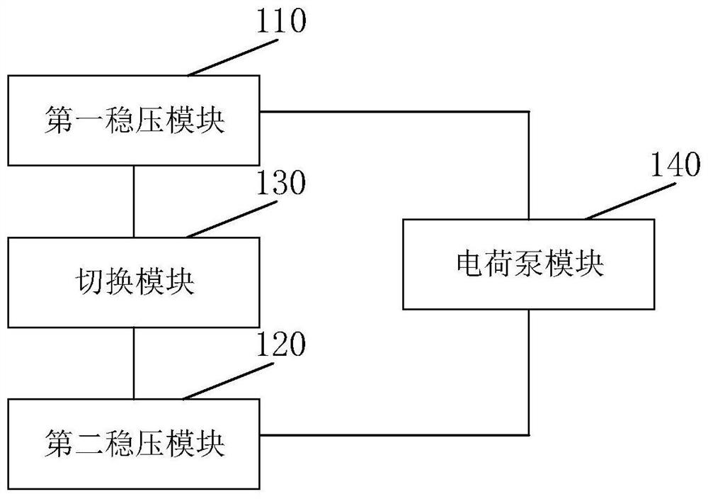
[0025] figure 2 It is a schematic structural diagram of the charge pump voltage stabilizing circuit in Embodiment 1 of the present invention. This embodiment is applicable to the situation of stabilizing the output voltage of the charge pump circuit, and the charge pump voltage stabilizing circuit is usually configured in a non-volatile memory.

[0026] Such as figure 2 As shown, the charge pump voltage stabilizing circuit provided in the embodiment of the present invention mainly includes the following parts: a first voltage stabilizing module 210 , a second voltage stabilizing module 220 , a switching module 230 and a charge pump module 240 .

[0027] The first voltage stabilizing module 210 is connected to the switching module 230 and the charge pump module 240 respectively, and is used to collect the first feedback voltage through the sampling resistor and generate the first control signal when receiving the first trigger signal, and output the first control signal to T...

Embodiment 2

[0059] Figure 5 It is a flow chart of the charge pump voltage stabilization method in Embodiment 2 of the present invention. This embodiment is applicable to the situation of stabilizing the output voltage of the charge pump circuit. The charge pump voltage stabilization method is provided by the charge pump voltage stabilization circuit provided in the above embodiment. execution, usually configured in non-volatile memory.

[0060] Such as Figure 5 As shown, the charge pump voltage stabilization method provided in the embodiment of the present invention mainly includes the following steps:

[0061] S510. The first voltage stabilizing module collects the first feedback voltage through a sampling resistor and generates a first control signal, and outputs the first control signal to the switching module and the charge pump module;

[0062] S520. The second voltage stabilizing module collects the second feedback voltage through the sampling capacitor and generates a second co...


PUM


Abstract

The invention discloses a charge pump voltage stabilizing circuit, a voltage stabilizing method and a nonvolatile memory, comprising: a first voltage stabilizing module generates a first control signal when receiving a first trigger signal; a second voltage stabilizing module receives a second The second control signal is generated when the trigger signal is generated; the switching module generates the first trigger signal according to the first control signal and the second control signal to trigger the working state of the first voltage stabilizing module, or generates the second trigger signal to trigger the second stabilizing The working state of the voltage module; the charge pump module controls the working state of the charge pump module according to the first control signal and the second control signal, so as to stabilize the load voltage output to the load. The technical solution provided by the embodiment of the present invention generates the first trigger signal and the second trigger signal through the switching module to trigger different voltage stabilizing modules to work, so that the load voltage output to the load is stable and the ripple amplitude of the load voltage is reduced.

Description

technical field [0001] The embodiments of the present invention relate to the technical field of integrated circuits, and in particular to a charge pump voltage stabilization circuit, a voltage stabilization method, and a nonvolatile memory. Background technique [0002] A charge pump is a DC-DC converter that uses a capacitor as an energy storage element to generate an output voltage greater than the input voltage, or to generate a negative output voltage. The instability of the output voltage will affect the reliability of the charge pump. Therefore, the charge pump needs to stabilize the output voltage during operation. [0003] figure 1 It is a charge pump regulator circuit commonly used in the prior art, figure 1 The working principle of the charge pump regulator circuit is as follows: the charge pump 101 generates the output voltage VOUT to provide energy for the load 103, and at the same time, the output voltage VOUT is divided by the resistor R1 and the resistor R2...

Claims


Application Information

Patent Timeline
IPC IPC(8): H02M3/07G11C5/14
CPCG11C5/145H02M3/07
Inventor 张现聚欧健孙锋锋
Owner GIGADEVICE SEMICON (BEIJING) INC
Why Eureka
Try Eureka