Dynamic harmonic suppression and reactive power compensation control system and control method thereof

A technology for harmonic suppression and control system, applied in reactive power compensation, reactive power adjustment/elimination/compensation, harmonic reduction devices, etc., which can solve the problems of reduced power supply capacity, low response speed requirements, and high power consumption. , to achieve the effect of improving power factor, ensuring power quality, and improving power supply capacity

Inactive Publication Date: 2013-02-20
ANHUI MINGYUAN POWER EQUIP MFR
View PDF0 Cites 0 Cited by
  • Summary
  • Abstract
  • Description
  • Claims
  • Application Information

AI Technical Summary

Problems solved by technology

There are inevitably problems such as large power consumption, temperature rise, and harmonic components called "electric pollution" that affect the long-term safe operation of the equipment. The life and reliability of the entire device cannot be effectively guaranteed, and even affect the entire normal operation of the grid
[0006] The load current provided by the grid to the electrical equipment includes active current and reactive current, and the reactive current is exchanged back and forth between the power supply and the load, which reduces the power factor of the grid power supply equipment and reduces the power supply capacity
[0007] The supporting automatic compensation core microcomputer control scheme has low control requirements, low requirements for signal processing and control response speed, and can only realize the function of capacitance compensation. The function is single and the level of intelligence is low. Industrial development needs

Method used


Image

  • Dynamic harmonic suppression and reactive power compensation control system and control method thereof
  • Dynamic harmonic suppression and reactive power compensation control system and control method thereof
  • Dynamic harmonic suppression and reactive power compensation control system and control method thereof

Examples


Embodiment Construction

[0054] Referring to the accompanying drawings, through the description of the embodiments, the specific implementation of the present invention, such as the shape, structure, mutual position and connection relationship between the various parts, the function and working principle of each part, and the manufacturing process And the method of operation and use, etc., are described in further detail to help those skilled in the art have a more complete, accurate and in-depth understanding of the inventive concept and technical solutions of the present invention.

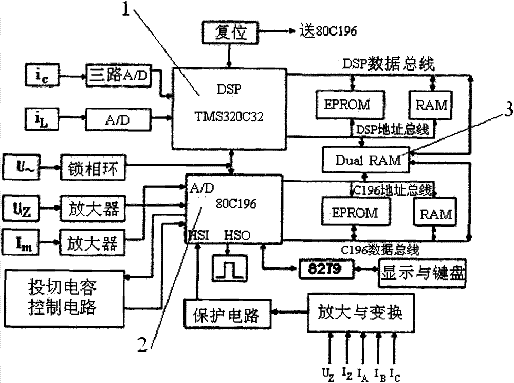
[0055] Such as figure 1 The structure of the present invention expressed is a dynamic harmonic suppression and reactive power compensation control system. Including a current signal sensor, the central control unit of the control system adopts a DSP chip 1 and a general-purpose single-chip microcomputer chip 2, and the data exchange between the described DSP chip 1 and the general-purpose single-chip microcomputer chip ...


PUM


Abstract

The invention discloses a dynamic harmonic suppression and reactive power compensation control system which comprises a current signal sensor, wherein a DSP (Digital Signal Processing) chip (1) and a general singlechip chip (2) are adopted in the central control unit of the control system, and the data interflow between the DSP chip (1) and the general singlechip chip (2) is transmitted by a bidirectional RAM (Random Access Memory) (3). The invention also discloses a control method adopted by the control system. By adopting the technical scheme, harmonic spectral analysis is carried out by utilizing load current detected in real time, the real-time control for a device is carried out according to a given control strategy, harmonic current in a load is filtered, and meanwhile, inductive reactive current in an electric network is rapidly and accurately counteracted in real time by the generated capacitive reactive current, thereby increasing the power factor, stabilizing the load voltage, ensuring the power quality, improving the power supply capability of power supply equipment and reducing the loss of the electric network.

Description

technical field [0001] The invention belongs to the technical field of electric power system, and relates to the technology of dynamic automatic compensation and harmonic control, more specifically, the invention relates to a dynamic harmonic suppression and reactive power compensation control system and its control method. Background technique [0002] With the rapid development of the national economy and the rapid increase of electricity consumption, the economic operation of the power grid has been paid more and more attention. Whether it is industrial load or civil load, most of them are perceptual. These inductive devices generate reactive power during operation, and the transformers and busbars in the transmission and distribution lines will cause power loss due to the transmission of reactive power. It is particularly important to reduce reactive power loss and increase the transmission power of the system. [0003] The load current provided by the grid to the elec...

Claims


Application Information

Patent Timeline
Patent Type & Authority Patents(China)
IPC IPC(8): H02J3/01H02J3/18
CPCY02E40/30Y02E40/40
Inventor 金苇杨柳
Owner ANHUI MINGYUAN POWER EQUIP MFR
Why Eureka
Try Eureka