Charging and discharging circuit based on half-bridge structure, and method

A charge-discharge circuit, charge-discharge technology, applied in battery circuit devices, circuit devices, current collectors, etc., can solve the problems of affecting sampling accuracy, temperature drift, voltage breakdown, etc., to increase stability and reliability, reduce Small ripple amplitude, the effect of reducing performance impact

Inactive Publication Date: 2017-07-21
江苏金帆电源科技有限公司
View PDF3 Cites 0 Cited by
  • Summary
  • Abstract
  • Description
  • Claims
  • Application Information

AI Technical Summary

Problems solved by technology

In the actual use process, due to the single-group PWM control, the bus filter electrolytic capacitors are in abnormal working conditions for a long time, which is easy to cause liquid leakage, voltage breakdown, capacitor failure, etc. Large current impact, if the voltage peak absorption capacitor performance decays, it will cause the IGBT module to work in an extreme state, and heat dissipation will become extremely difficult as the thermal grease on the heat dissipation surface ages; as we all know, the reactor must be designed according to the current specification , the 40 ampere reactor is very bulky, causing troubles to the structural design; in addition, the single shunt used for sampling has a large output ripple current, which makes it generate serious heat, resulting in temperature drift, which affects its sampling precision

Method used


Image

  • Charging and discharging circuit based on half-bridge structure, and method
  • Charging and discharging circuit based on half-bridge structure, and method
  • Charging and discharging circuit based on half-bridge structure, and method

Examples


Embodiment Construction

[0016] A specific implementation of the charging and discharging circuit and method based on the half-bridge structure of the present invention will be described in detail below with reference to the accompanying drawings.

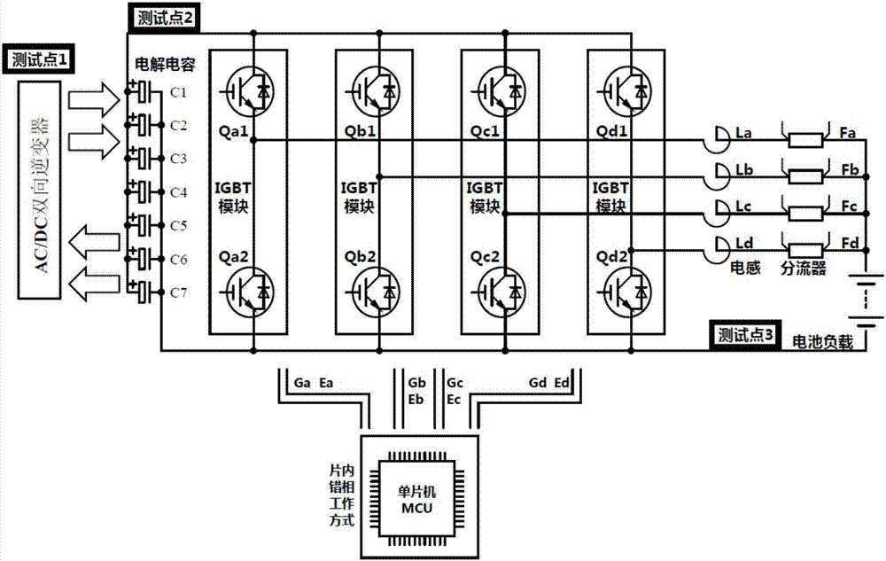
[0017] Such as figure 1 As shown, the charging and discharging circuit based on the half-bridge structure using on-chip wrong-phase drive (a single-chip microcomputer), including: AC / DC bidirectional inverter, bus filter connected in parallel on the DC output of the AC / DC bidirectional inverter circuit, and four charging and discharging units connected in parallel (the number of charging and discharging units can be determined according to the actual situation, and can also be three or five or even more), and the phase angles provided for these four charging and discharging units are mutually Staggered PWM out-of-phase drive circuit (since it is four-way out-of-phase output, the phase angles of the sequential outputs differ by 90 degrees), the bus filter ...


PUM


Abstract

The invention discloses a charging and discharging circuit based on a half-bridge structure, wherein the circuit can improve the working states of an IGBT module, a bus filtering circuit and an electric reactor. The circuit comprises an AC / DC bidirectional inverter, the bus filtering circuit, at least three charging and discharging units in parallel connection, and a PWM staggered phase drive circuit with the mutually staggered phases. Each charging and discharging unit comprises a first IGBT module and a second IGBT module, wherein the collector electrode of the first IGBT module is connected with the DC positive electrode of the AC / DC bidirectional inverter, and the emitter electrode of the first IGBT module is connected with the collector electrode of the second IGBT module. The emitter electrode of the second IGBT module is connected with the DC negative electrode of the AC / DC bidirectional inverter. The output ends of the charging and discharging units are in series connection with the matched electric reactors, and then are connected in parallel. The invention also discloses a corresponding charging and discharging method. The circuit and method are mainly used for the charging and discharging of a storage battery.

Description

technical field [0001] The invention relates to a charging and discharging circuit, in particular to a circuit and method for charging and discharging a storage battery based on a half-bridge structure. Background technique [0002] Such as image 3 As shown, the traditional charging and discharging circuit based on the half-bridge structure includes: AC / DC bidirectional inverter, bus filter electrolytic capacitor, single-group charging and discharging circuit composed of 150A / 600V IGBT module and single-group charging and discharging circuit. The discharge circuit corresponds to a single set of PWM trigger circuit, a single 40A reactor and a single 40A / 75mV shunt. In the actual use process, due to the single-group PWM control, the bus filter electrolytic capacitors are in abnormal working conditions for a long time, which is easy to cause liquid leakage, voltage breakdown, capacitor failure, etc. Large current impact, if the voltage peak absorption capacitor performance de...

Claims


Application Information

Patent Timeline
Patent Type & Authority Applications(China)
IPC IPC(8): H02J7/04H02M1/14
CPCH02J7/045H02M1/14
Inventor 徐利东闵卫丰
Owner 江苏金帆电源科技有限公司
Why Eureka
Try Eureka