
Multifunctional universal led driver

Active Publication Date: 2015-12-24
BAHREHMAND FARHAD
View PDF0 Cites 105 Cited by
  • Summary
  • Abstract
  • Description
  • Claims
  • Application Information

AI Technical Summary

Benefits of technology

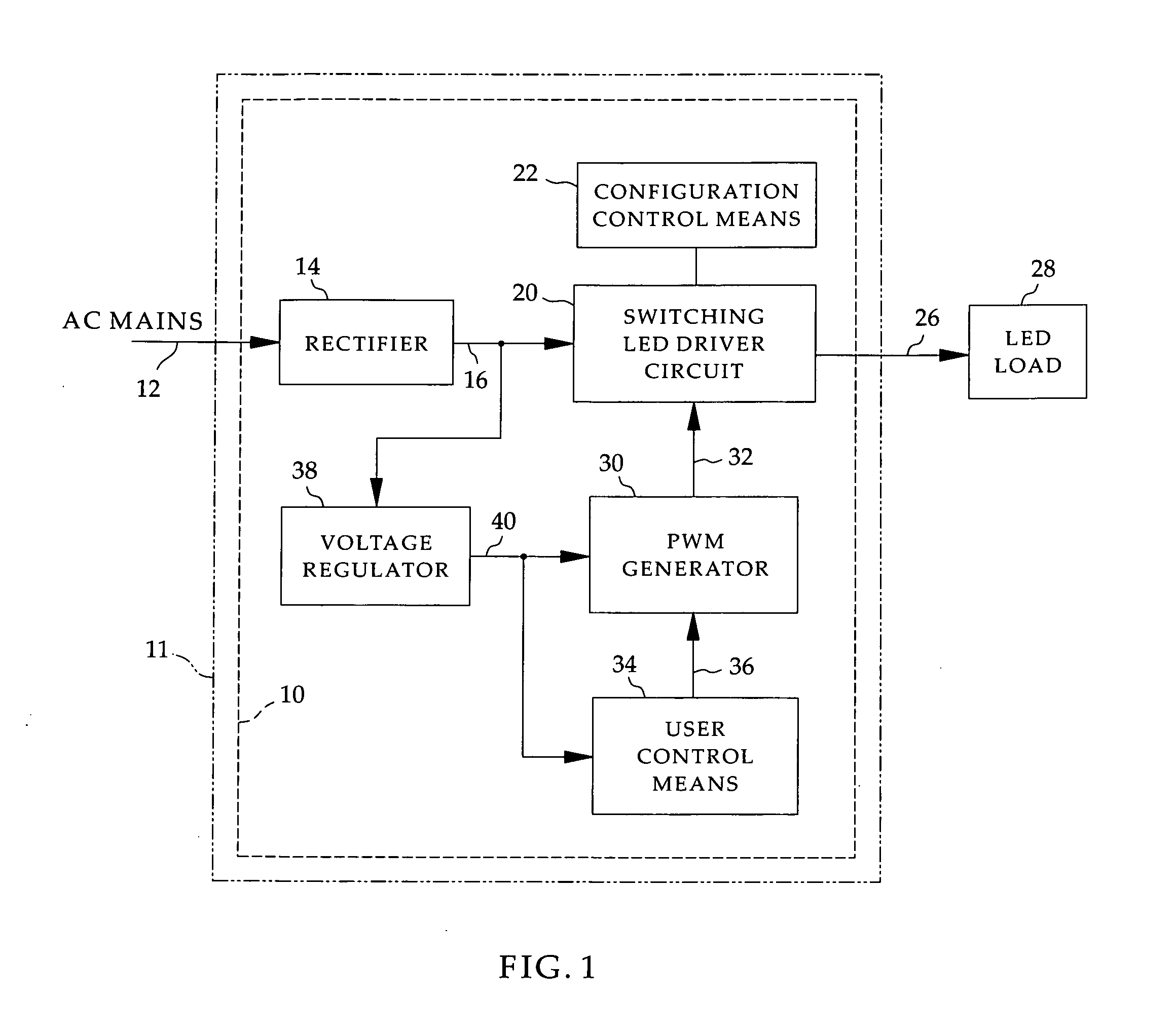
The present invention relates to an LED driver that can be easily installed in an AC outlet box and controlled by a user control means. The user control means can be a small button or a remote controller, and the LED driver can be controlled through an interface on the enclosure faceplate. The LED driver can also be controlled through a configuration control means that can be adjusted by the end user to match the voltage and current requirements of the LED load. The configuration control means can be password protected. The LED driver can also use a wireless protocol, such as Wi-Fi or Bluetooth, for controlling the output. The LED driver can also have a motion detection circuit to turn the LED load on when motion is detected. The LED driver can also have a real-time clock to keep track of the current time.

Problems solved by technology

The disadvantages (at least when compared to 110V tungsten light bulbs) are that they cannot directly replace incandescent lamps, and, a single LED is very small and generally cannot generate enough light to light up a room.
If the LED's are driven by higher currents and voltage than their rated values, their life span will significantly shorten or they may even burn out quickly.
Currently, the LED drivers used by lighting companies for fixtures such as chandeliers are so large they can barely fit into the ceiling or fixture canopy.
This is an awkward way of solving the problem because two units have to be installed, one in the ceiling and one in the wall outlet for the fixture.
In addition, there are compatibility issues between LED drivers and incandescent dimmers.
The LED driver cannot be configured by an end user.
Additionally, the LED driver does not directly connect to AC mains and cannot be installed in a standard AC outlet.
While this design could be used for dimming LED's, it does not disclose a technology as how to power, dim, and switch LED's on / off in an offline application that could also be fit in an AC outlet for lighting applications.
None of the above items of prior art disclose or suggest a means for configuring the output characteristics of the LED driver by an end user.

Method used


Image

  • Multifunctional universal led driver
  • Multifunctional universal led driver
  • Multifunctional universal led driver

Examples


Embodiment Construction

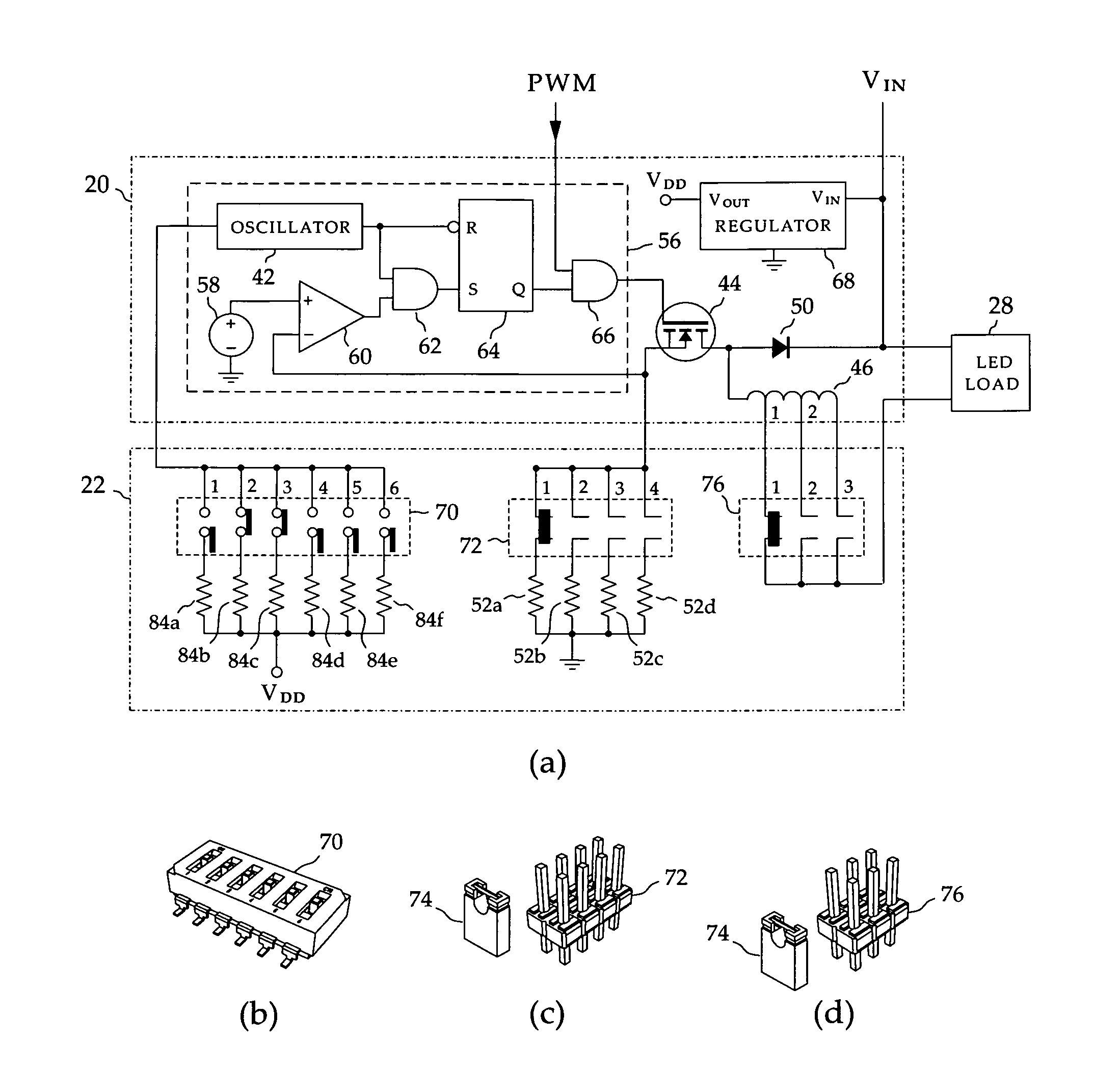
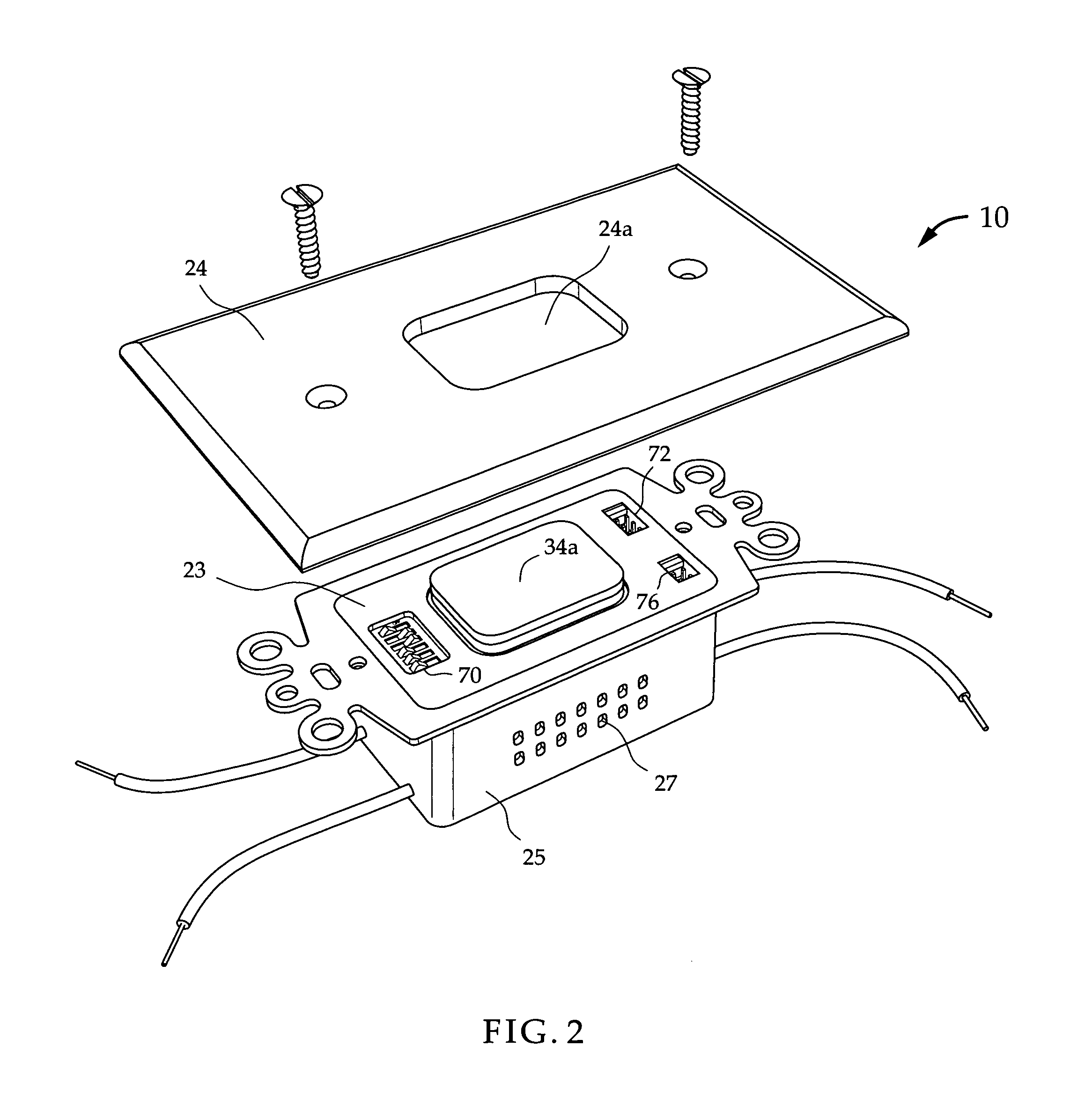
[0087]The present invention resides in a universal multi-function LED driver with integrated switch and preferably dimmer that can be configured to match the voltage and current requirements of an LED load. The term universal signifies that the same design can be adapted to operate globally with different AC line voltages with no need for an external adapter. The LED driver employs one or more programmable integrated circuits; therefore, the disclosed LED driver is programmable. The configurable multi-function LED driver, in one embodiment, is intended for installation in a standard AC outlet and connects directly to the existing wiring in the AC outlet with no need for making changes to the existing wiring. The output voltage and / or the output current of the LED driver are configurable using one or more switches installed, in this embodiment, on the housing or under the faceplate of the finished product so that they can be preset by a user to match the specific voltage and current ...


PUM


Abstract

A multifunctional universal LED driver is disclosed that can be configured to match the voltage and / or current requirements of various LED loads such as LED lighting fixtures. The disclosed LED driver replaces the existing wall switch to drive an LED lighting fixture with no need for making changes to the existing wires. The user control means are installed in the faceplate of the LED driver and are relatively accessible to an end user. The configuration control means are installed so as to be relatively inaccessible to an end user during normal operation of the LED driver. In a wireless embodiment, a wireless remote controller operates the LED driver. In another wireless embodiment, the remote controller is a computing platform such as a smartphone, which can configure, operate, and query the status of the LED driver. The status of the LED driver may include on / off, intensity level, energy being consumed by the LED load, configuration settings, and other useful information such as serial number, manufacturing date, country of origin, and ratings. The Wi-Fi embodiment of the LED driver enables the LED driver to be controlled using the Internet and become part of the network of Internet of Things (IoT).

Description

RELATED APPLICATIONS[0001]This current application is a utility application and claims the benefit of U.S. Provisional application No. 61 / 957,282, filed Jun. 28, 2013, titled “Multi-Function Universal LED Driver”. This current application also claims the benefit of the following pending application and two issued U.S. patents:[0002]1. Patent application Ser. No. 12 / 324,200, filed Nov. 26, 2008, titled “LED Driver and Integrated Dimmer and Switch;[0003]2. U.S. Pat. No. 8,344,639 B1, filed Jan. 31, 2010, issued Jan. 1, 2013, titled “Programmable LED Driver”;[0004]3. U.S. Pat. No. 8,575,851 B1, filed Dec. 27, 2012, issued Nov. 5, 2013, titled “Programmable LED Driver”.The disclosures of the aforementioned Issued Patents and Patent Applications are hereby incorporated herein by reference hereto.BACKGROUND OF THE INVENTION[0005]1. Technical Field[0006]The present invention relates to an LED (light emitting diode) driver with control means configurable by an end user of the driver to matc...

Claims


Application Information

Patent Timeline
IPC IPC(8): H05B33/08H05B37/02H05B44/00
CPCH05B33/0815H05B37/0272H05B33/0803H05B37/0227H05B33/0848H05B45/14H05B47/19Y02B20/40H05B45/325H05B47/115H05B47/13H05B47/195H05B45/375H05B47/11
Inventor BAHREHMAND, FARHAD
Owner BAHREHMAND FARHAD
Learn More