Lead extraction

Inactive Publication Date: 2015-12-31
LEADR MEDICAL
View PDF7 Cites 5 Cited by
  • Summary
  • Abstract
  • Description
  • Claims
  • Application Information

AI Technical Summary

Benefits of technology

[0073]reducing the diameter of the first grasping portion includes reducing the diameter of the first grasping portion by rotating a proximal end of a control tube, inside of which the grasping tube is disposed, in a first direction,

Problems solved by technology

In some situations, an implanted lead, such as a cardiac pacemaker le

Method used


Image

  • Lead extraction
  • Lead extraction
  • Lead extraction

Examples


Embodiment Construction

[0087]Before referring to the figures, a general introduction to the present description is provided.

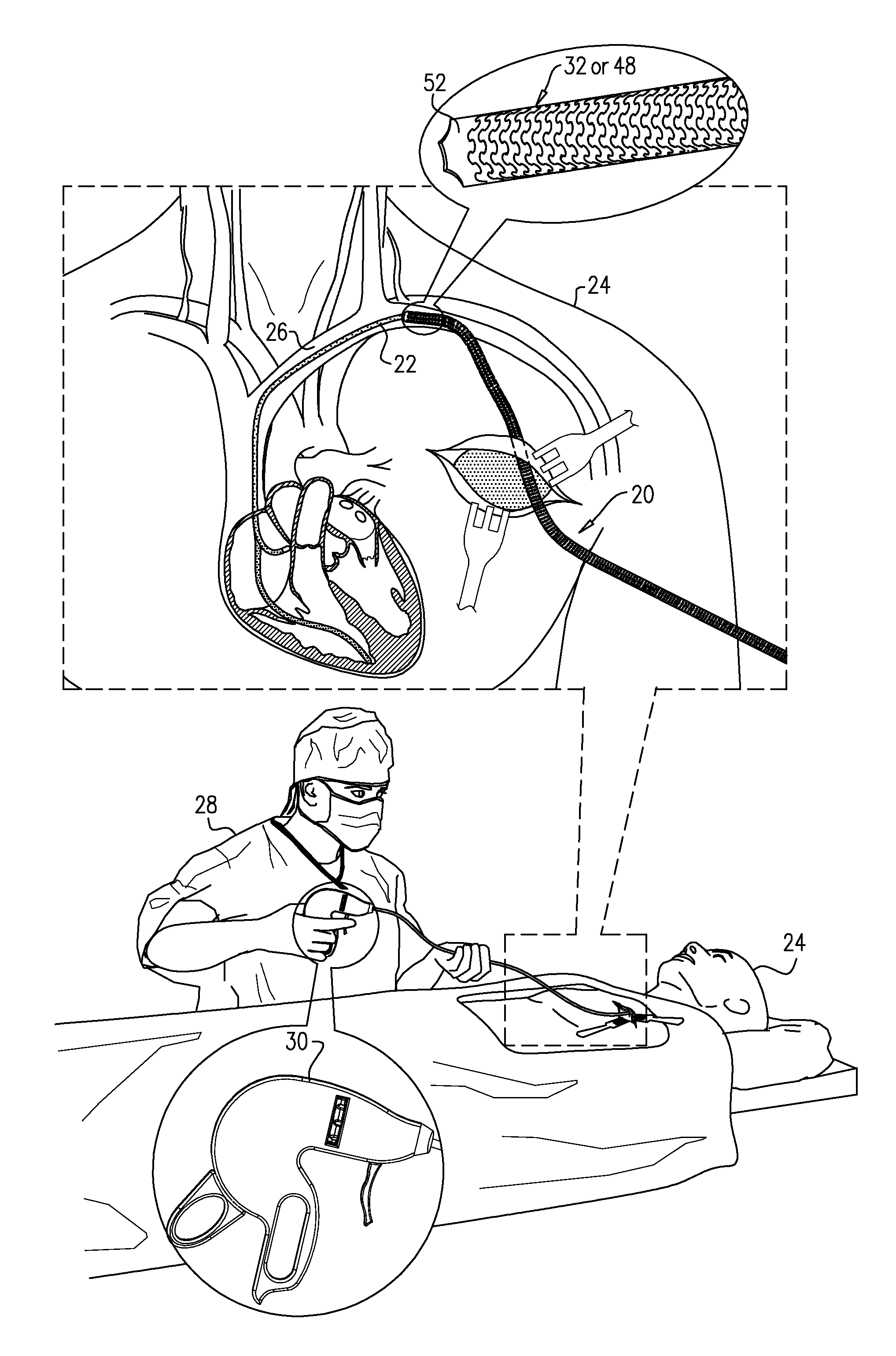
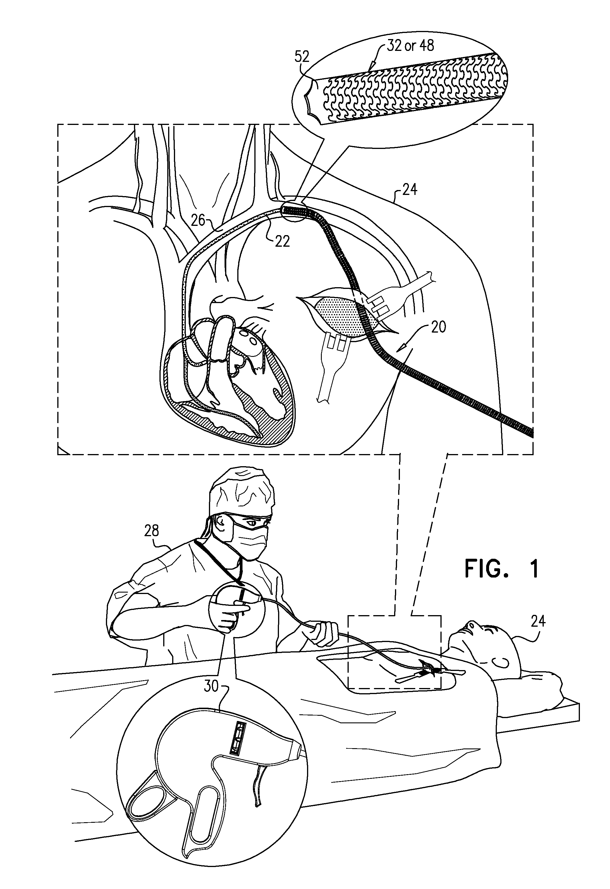
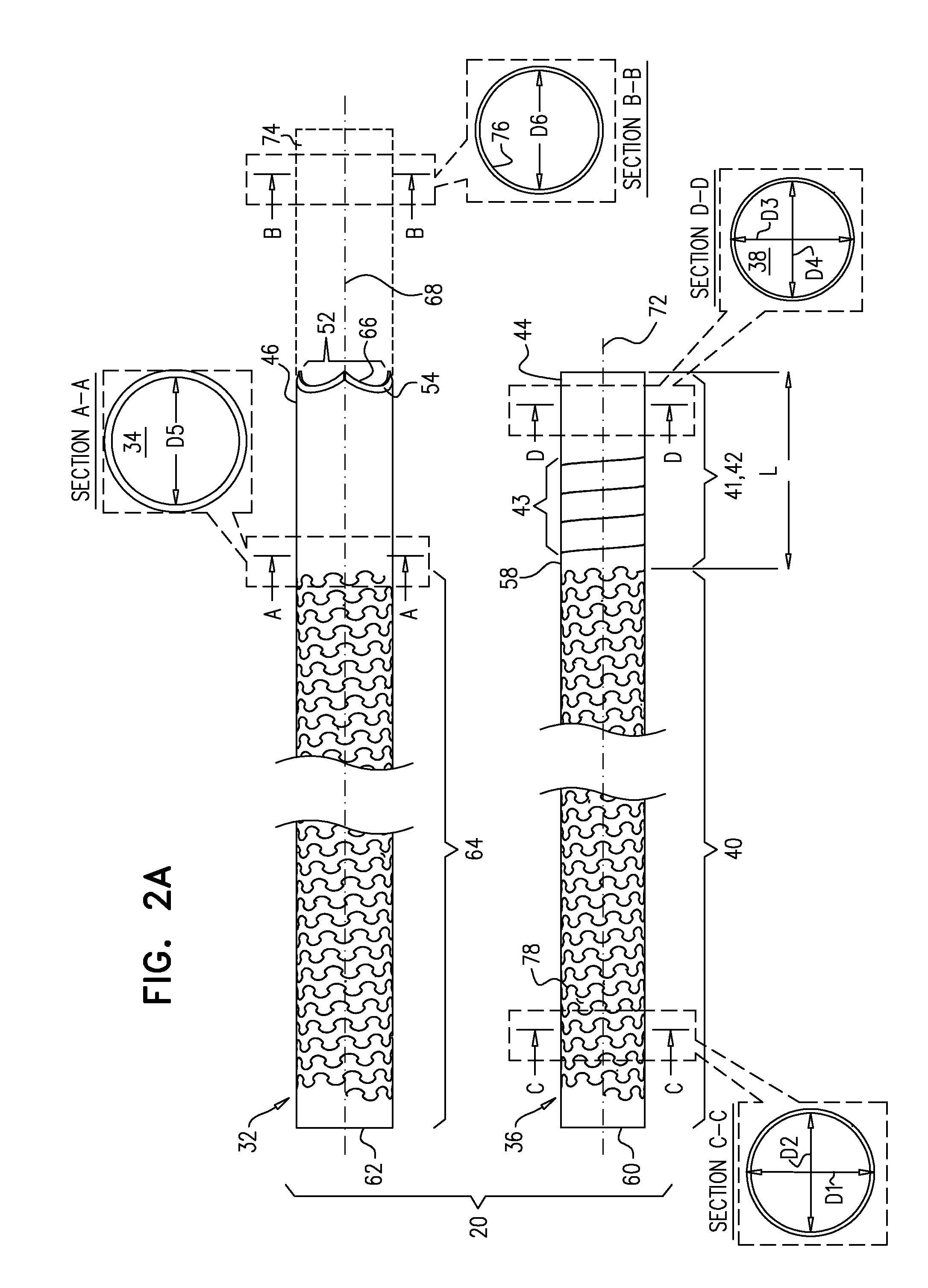
[0088]Applications of the present invention provide apparatus and methods for removing a lead (e.g., a cardiac pacemaker lead) from a lumen (e.g., a blood-vessel lumen) of a subject. Generally, as described hereinbelow, one or more substantially concentric tubes are advanced through the lumen toward a distal portion of the lead, such that, upon reaching the distal portion of the lead, substantially all of the lead is contained inside a lumen of the innermost tube. Typically, the lead is grasped multiple times as the tubes are advanced, thus facilitating advancement of the tubes in a controlled manner, and reducing undesired backward movement of the tubes. The lead is then grasped at the distal portion thereof, and removed from the lumen. Grasping the lead includes reducing a diameter of one or more grasping portions that are near the distal end of the innermost tube. The grasping por...


PUM


Abstract

Apparatus for removing a lead from a lumen of a subject including a flexible control tube shaped to define a control-tube lumen; and a flexible grasping tube shaped to define a grasping-tube lumen. The grasping tube is disposed within the control-tube lumen and includes a torque-transfer non-distal portion; and a helically-cut distal portion, that is (a) fixed at a distal end thereof to a distal end of the control tube, and (b) rotatable at least at a proximal end thereof with respect to the control tube. The helically-cut distal portion is configured to grasp the lead within the grasping-tube lumen upon the proximal end of the helically-cut distal portion being rotated with respect to the control tube.

Description

FIELD OF THE INVENTION[0001]The present invention relates to apparatus and methods for extracting a lead, such as a cardiac pacemaker lead, from a subject.BACKGROUND[0002]In some situations, an implanted lead, such as a cardiac pacemaker lead, may stop working, or an infection may set in at the implant site. In such situations, it may be desired to extract the lead from the subject.SUMMARY OF THE INVENTION[0003]Applications of the present invention provide apparatus for removing a lead (e.g., a cardiac pacemaker lead) from a lumen (e.g., a blood-vessel lumen) of a subject. The apparatus includes at least two tubes: a flexible control tube, and a flexible grasping tube disposed within a lumen of the control tube. The flexible grasping tube includes a torque-transfer non-distal portion and a helically-cut distal portion. The helically-cut distal portion is fixed at a distal end thereof to a distal end of the control tube, and is rotatable at least at a proximal end thereof with respec...

Claims


Application Information

Patent Timeline
IPC IPC(8): A61B17/32
CPCA61B17/32002A61B2017/00243A61B17/50A61B2017/00309A61N2001/0578A61B17/320016A61B17/32053A61B2017/320032
Inventor TOBIS, IDAN
Owner LEADR MEDICAL
Why Eureka
Try Eureka