Method for reducing interference from scattered light/reflected light of interference path by generating carrier through phase
- Summary
- Abstract
- Description
- Claims
- Application Information
AI Technical Summary
Benefits of technology
Problems solved by technology
Method used
Image
Examples
Example
REFERENCE NUMERAL
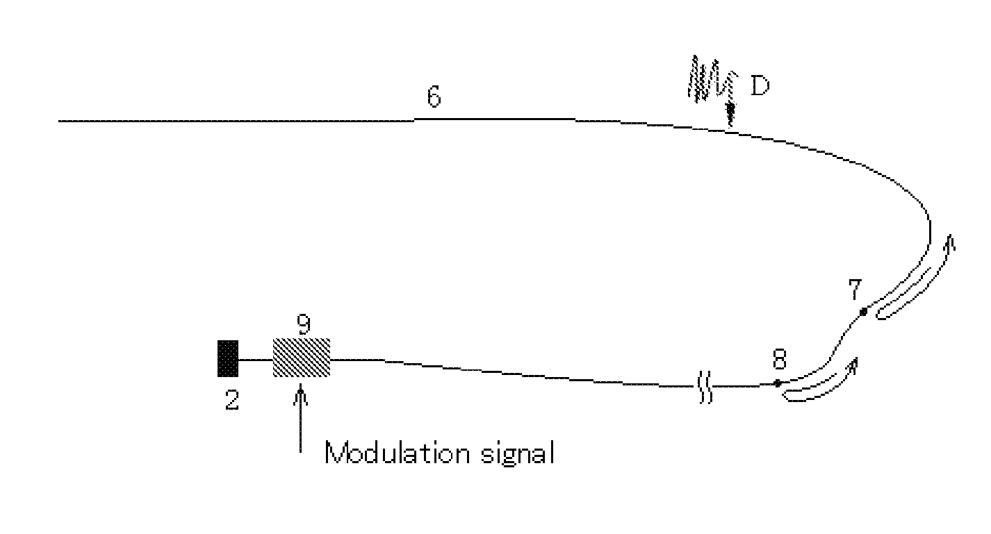
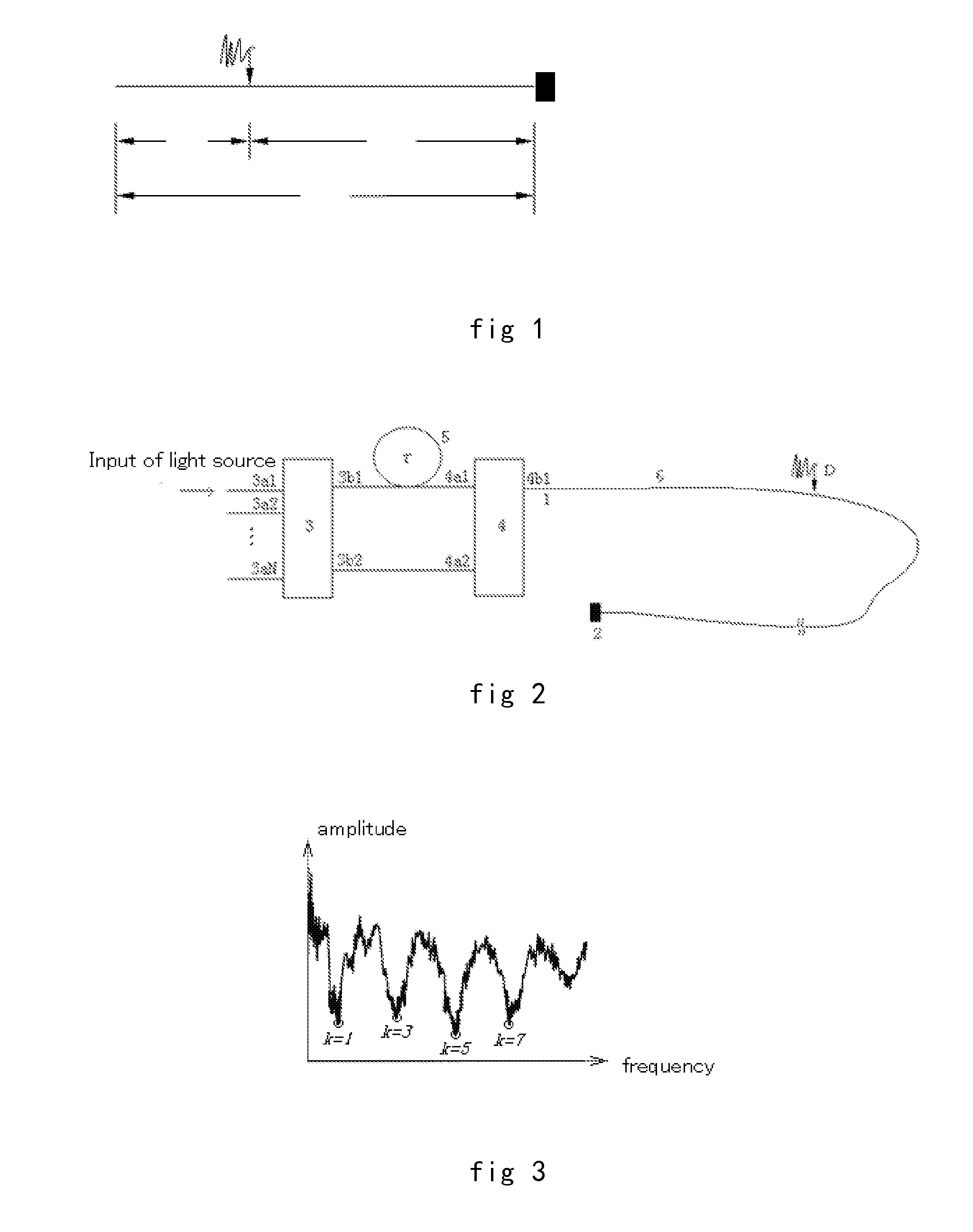
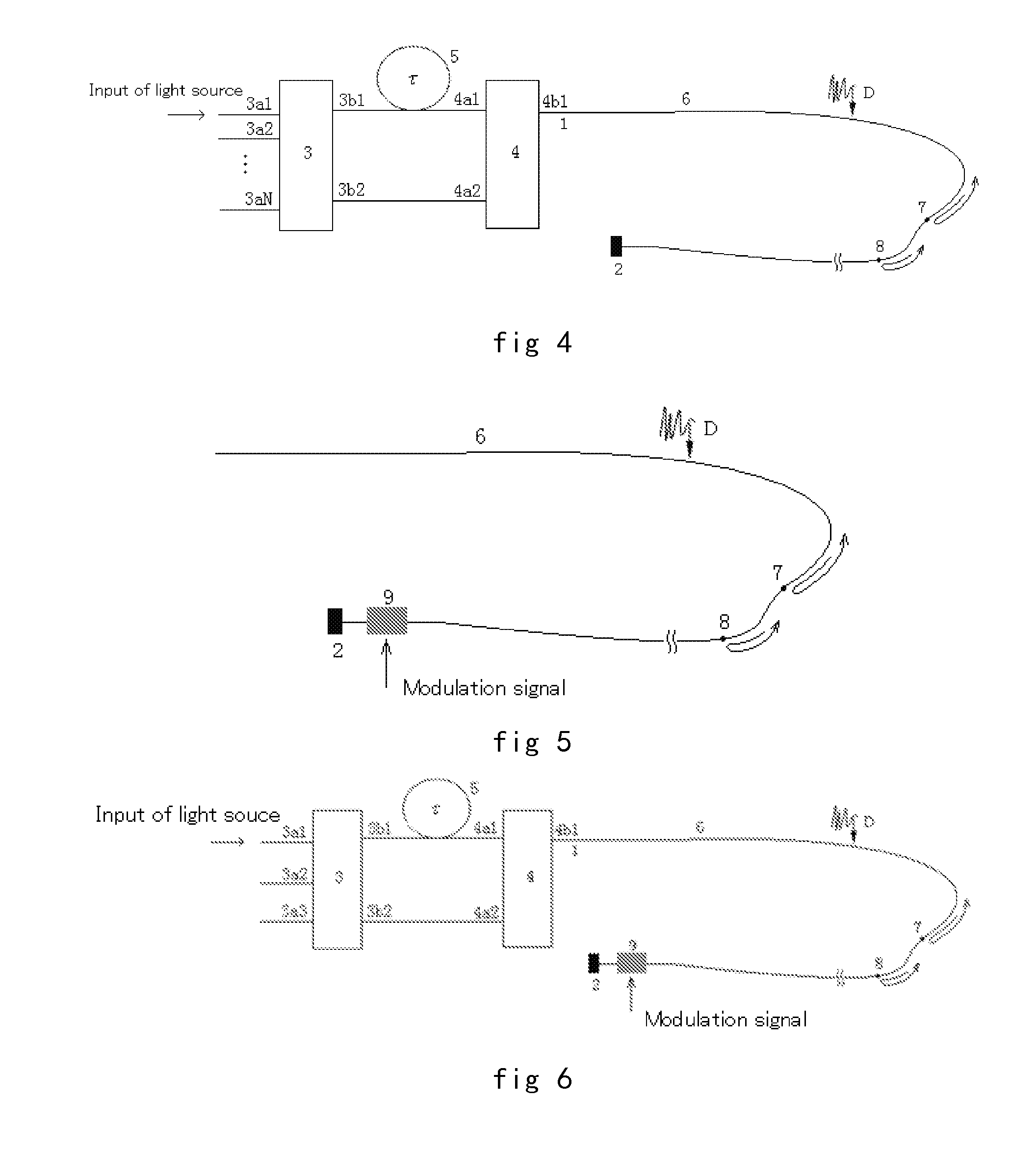
[0060]1: end of the sensing optical fiber 6, 2: feedback device, 3: for the N * M (N, M are integers) coupler, 4: P * Q (P, Q are integers) coupler, 5: optical fiber delayer, delay τ, 6: sensor optical fiber (optical cable) and feedback device 2 constituted, 3a1, 3a2, . . . , 3aN, 3b1, 3b2: port of coupler 3, 3a1, 3a2, . . . , 3aN: co-rotating ports with a total of N, 3b1, 3b2: two ports in another group co-rotating ports (with a total of M) of coupler 3. 4a1, 4a2, 4b1: ports of coupler 4, 4a1, 4a2: two ports in a group co-rotating ports (with a total of P) of coupler 4, 4b1: two ports in another group co-rotating ports (with a total of Q) of coupler 4. 7, 8: scattering point in optical fiber, 9: phase modulator.
Embodiment
[0061]The measurement system of the embodiment use interference structure shown in FIG. 3. Length of sensing optical cable 6 is 30 km. Light source is S03-B type super super radiation diode (SLD) produced by 44 research institute of the Institute o...
PUM
 Abstract
Description
Claims
Application Information
 - R&D
- Intellectual Property
- Life Sciences
- Materials
- Tech Scout
- Unparalleled Data Quality
- Higher Quality Content
- 60% Fewer Hallucinations
Browse by: Latest US Patents, China's latest patents, Technical Efficacy Thesaurus, Application Domain, Technology Topic, Popular Technical Reports.
© 2025 PatSnap. All rights reserved.Legal|Privacy policy|Modern Slavery Act Transparency Statement|Sitemap|About US| Contact US: help@patsnap.com


