Backlight, display device and method for controlling backlighting thereof

Active Publication Date: 2015-12-31
BOE TECH GRP CO LTD +1
View PDF3 Cites 7 Cited by
  • Summary
  • Abstract
  • Description
  • Claims
  • Application Information

AI Technical Summary

Benefits of technology

[0009]The present disclosure provides a backlight, a display device and a method for controlling backlighting thereof. The backlight comprises a backplate and a light emitting unit which is arranged on a surface of the backplate. The light emitting unit comprises a substrate and a plurality of light sources which are fixed onto the substrate. The substrate comprises an attached part which is fixed to a central area of the surface of the backplate and a bendable part which forms a preset angle with a non-central

Problems solved by technology

In addition, in the practical observation, this will result in a non-uniform bright

Method used


Image

  • Backlight, display device and method for controlling backlighting thereof
  • Backlight, display device and method for controlling backlighting thereof
  • Backlight, display device and method for controlling backlighting thereof

Examples


first embodiment

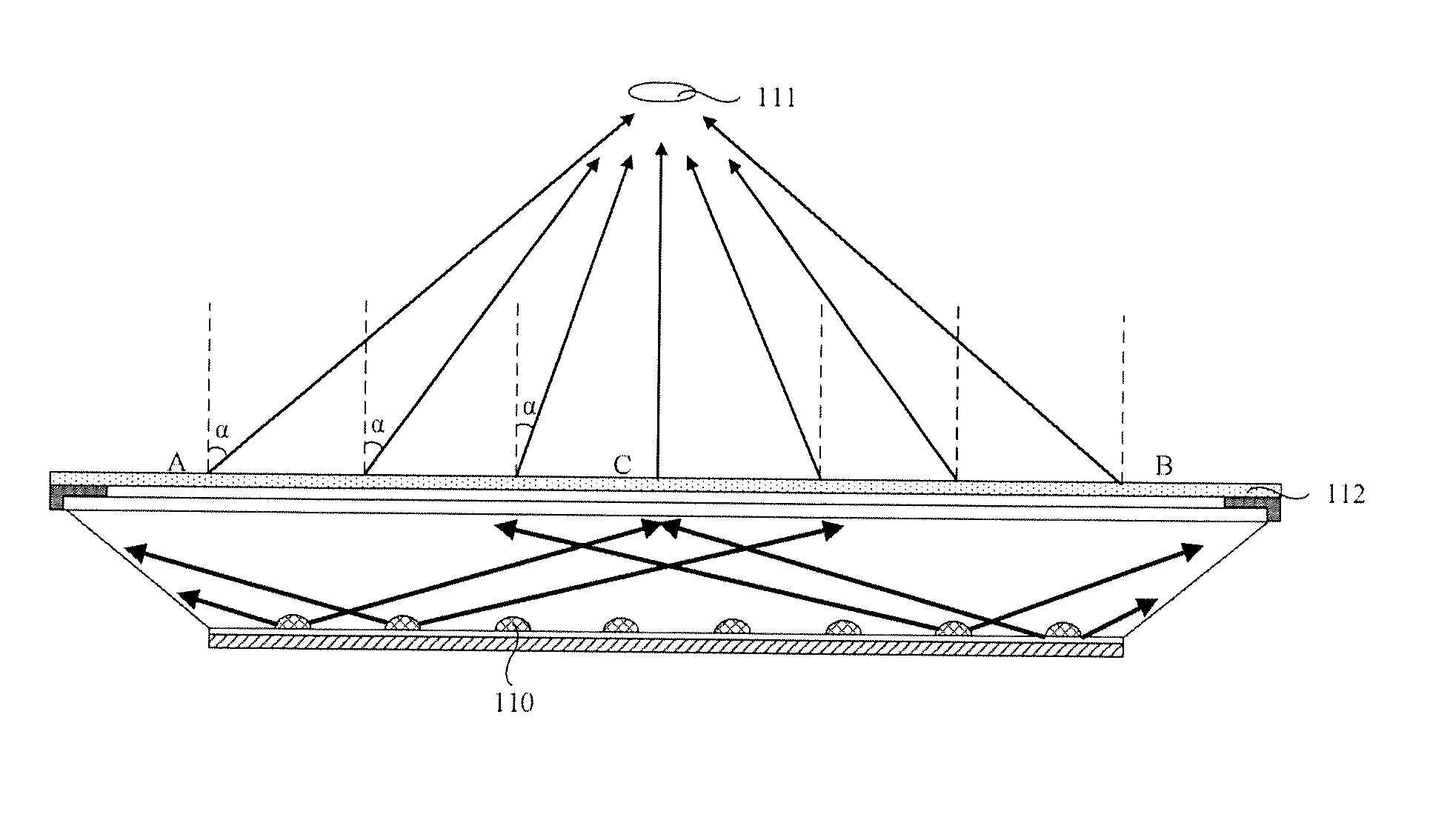
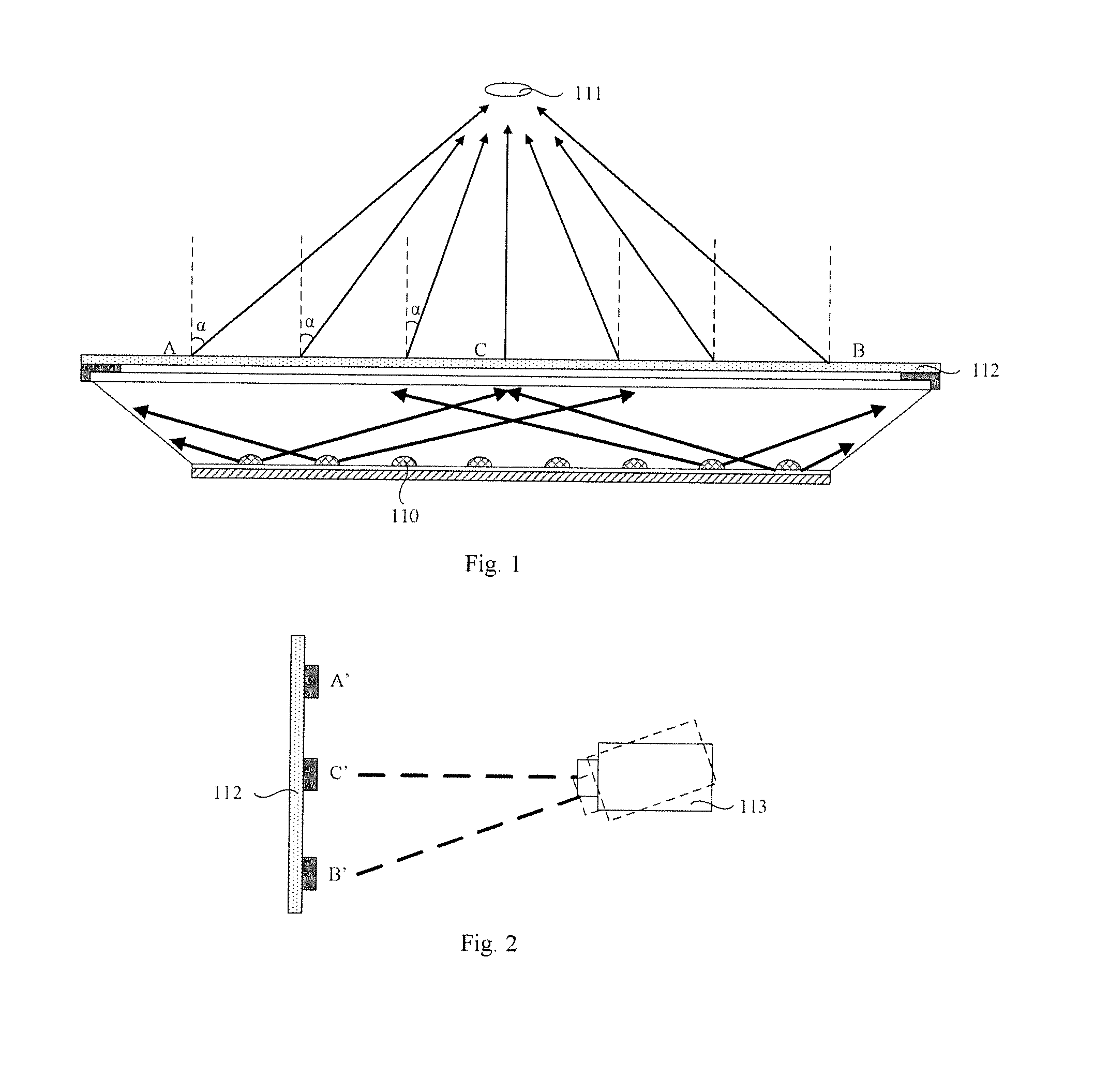
[0037]When the backlight is adopted in a display device, and the distance between human eyes 111 or the test equipment 113 and the display device is relatively small, the first magnetic field component 2012 and the second magnetic field component 2013 can be separated from each other to maintain the preset angle β. As a result, the light emitting unit 201 can compensate light ray at areas of two ends of the display panel 112 where there is less light ray by using the bendable part 2011 (areas where point A and point B are located in FIG. 1). Thus, light ray which is emitted by the backlight and perceived by human eyes 111 or the test equipment 113 is uniformly distributed. When the distance between human eyes 111 or the test equipment 113 and the display device increases gradually, differences among angles between each light ray which is perceived by human eyes 111 or the test equipment 113 and the normal of the display panel 112 decreases gradually. Therefore, the first magnetic fi...

second embodiment

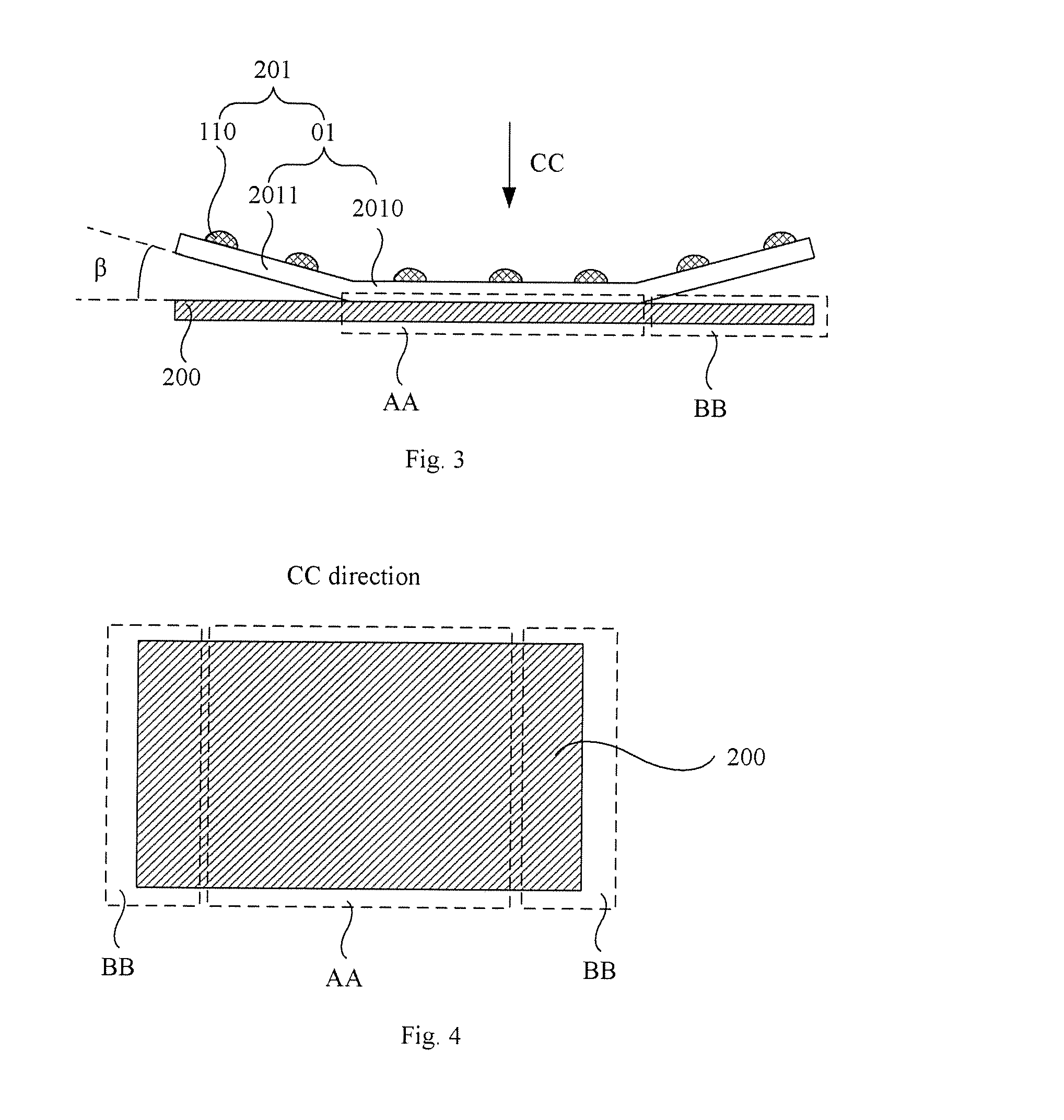
[0041]In case the first magnetic field component 2012 and / or the second magnetic field component 2013 is composed of an electromagnet, it is also possible to control the magnitude of current to control the separating / attaching state, so as to control the magnitude of the preset angle β. For instance, as shown in FIG. 6, in case that the first magnetic field component 2012 covers the whole surface of the bendable part 2011 which is close to the backplate 200, the second magnetic field component 2013 covers the whole surface of the backplate 200 which is close to the bendable part 2011, the first magnetic field component 2012 is composed of a ferrous coating, and the second magnetic field component 2013 is composed of an electromagnet, it is possible to control the current which is fed into the second magnetic field component 2013 so as to control the magnitude of the preset angle β. Particularly, when the observation distance H1 increases gradually, it is possible to increases gradua...

third embodiment

[0052]As shown in FIG. 6, in case that the first magnetic field component 2012 covers the whole surface of the bendable part 2011 which is close to the backplate 200, the second magnetic field component 2013 covers the whole surface of the backplate 200 which is close to the bendable part 2011, the first magnetic field component 2012 is composed of a ferrous coating, and the second magnetic field component 2013 is composed of an electromagnet, when the observation distance H1 increases gradually, the angle controlling unit 300 can increase gradually the current which is fed into the second magnetic field component 2013. In this manner, a portion of the first magnetic field component 2012 which is close to the second magnetic field component 2013 is attracted to the second magnetic field component 2013. As the current further increases, a portion of the first magnetic field component 2012 which is far from the second magnetic field component 2013 is gradually attracted to the second ...


PUM


Abstract

The present disclosure provides a backlight, a display device and a method for controlling backlighting thereof. The present disclosure relates to the field of display technology, and enables a display panel with uniform brightness. The backlight comprises a backplate and a light emitting unit which is arranged on a surface of the backplate. The light emitting unit comprises a substrate and a plurality of light sources which are fixed onto the substrate. The substrate comprises an attached part which is fixed to a central area of the surface of the backplate and a bendable part which forms a preset angle with a non-central area of the surface of the backplate.

Description

FIELD OF THE INVENTION[0001]The present disclosure relates to the field of display technology, and particularly to a backlight, a display device and a method for controlling backlighting thereof.BACKGROUND OF THE INVENTION[0002]A LCD (liquid crystal display) is a passive light emitting device, in which a BLU (Backlight Unit) is required to provide a light source for enabling the LCD to display an image. Currently, the popular backlights for LCD comprise CCFL (cold cathode fluorescent lamp) and LED (light emitting diode). LED has been increasingly accepted as a backlight due to its advantages of high brightness, high color purity, long service life, high reliability, and free from mercury pollution.[0003]A LED backlight can be classified into a direct type and a side type. In the side type, the light source is placed at a side of the display panel. In the direct type, the light source is arranged at a lower surface (i.e., the non-display surface) of the display panel. Particularly, a...

Claims


Application Information

Patent Timeline
IPC IPC(8): G02F1/1335
CPCG02F1/133602G02F2001/133613G02F1/133603G02F1/133611G02F1/133613
Inventor JIA, ZHISHUAIFU, CHANGGUI
Owner BOE TECH GRP CO LTD
Why Eureka
Try Eureka