Antenna control method and antenna control system

a control method and control system technology, applied in the field of antenna control methods and the control system of antennas, can solve the problems of difficult introduction and donor antennas cannot serve the function of relaying, and achieve the effect of reducing installation and maintenance management costs and improving communication quality

Inactive Publication Date: 2015-12-31
HIWAVE +1
View PDF5 Cites 22 Cited by
  • Summary
  • Abstract
  • Description
  • Claims
  • Application Information

AI Technical Summary

Benefits of technology

[0030]In the antenna control system and the method according to the present invention, an antenna direction is optimally and automatically set based on analysis results of signal quality parameters received from various directions, so that a communication quality can be improved and installation and maintenance management costs can be reduced as compared with manually adjusting an antenna orientation direc

Problems solved by technology

In this case, there is a problem that irregular reflection caused by wall surfaces of the building and indoor structures makes it difficult to bring a facing state to the base station into an optimum state, and a reflected wave of the irregular reflection is fed back to another antenna, namely the service antenna, of the mobile commun

Method used


Image

  • Antenna control method and antenna control system
  • Antenna control method and antenna control system
  • Antenna control method and antenna control system

Examples


Embodiment Construction

[0044]Various embodiments of the present invention will be described in detail below with reference to the attached drawings. However, it is to be noted that the technical scope of the present invention is not limited to the described embodiments and encompasses the invention and equivalents described in a scope of claims.

[0045]Further, it is to be understood by those skilled in the art that various modifications, substitutions, and corrections of the embodiments can be made without departing from the scope and spirit of the present invention.

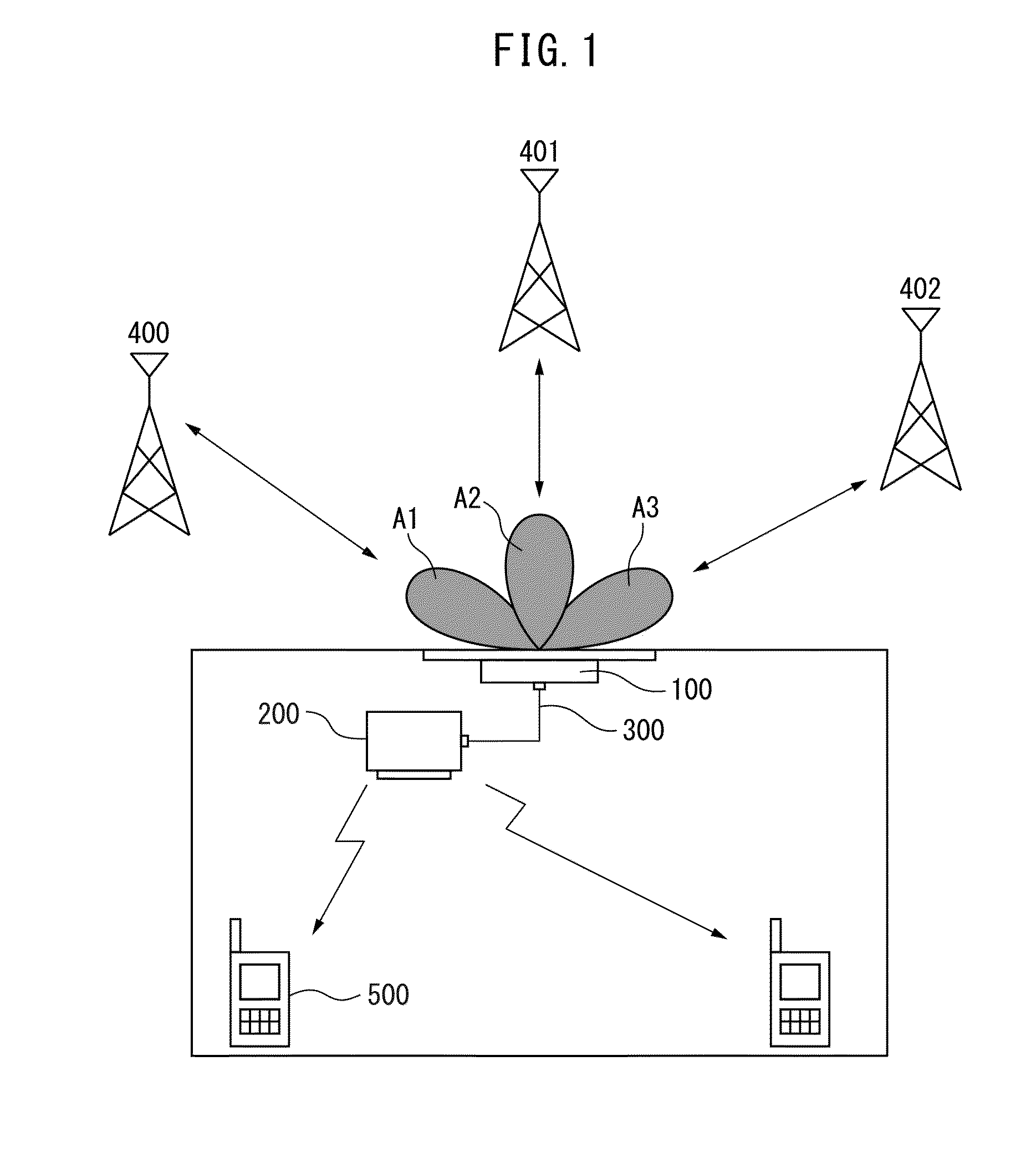
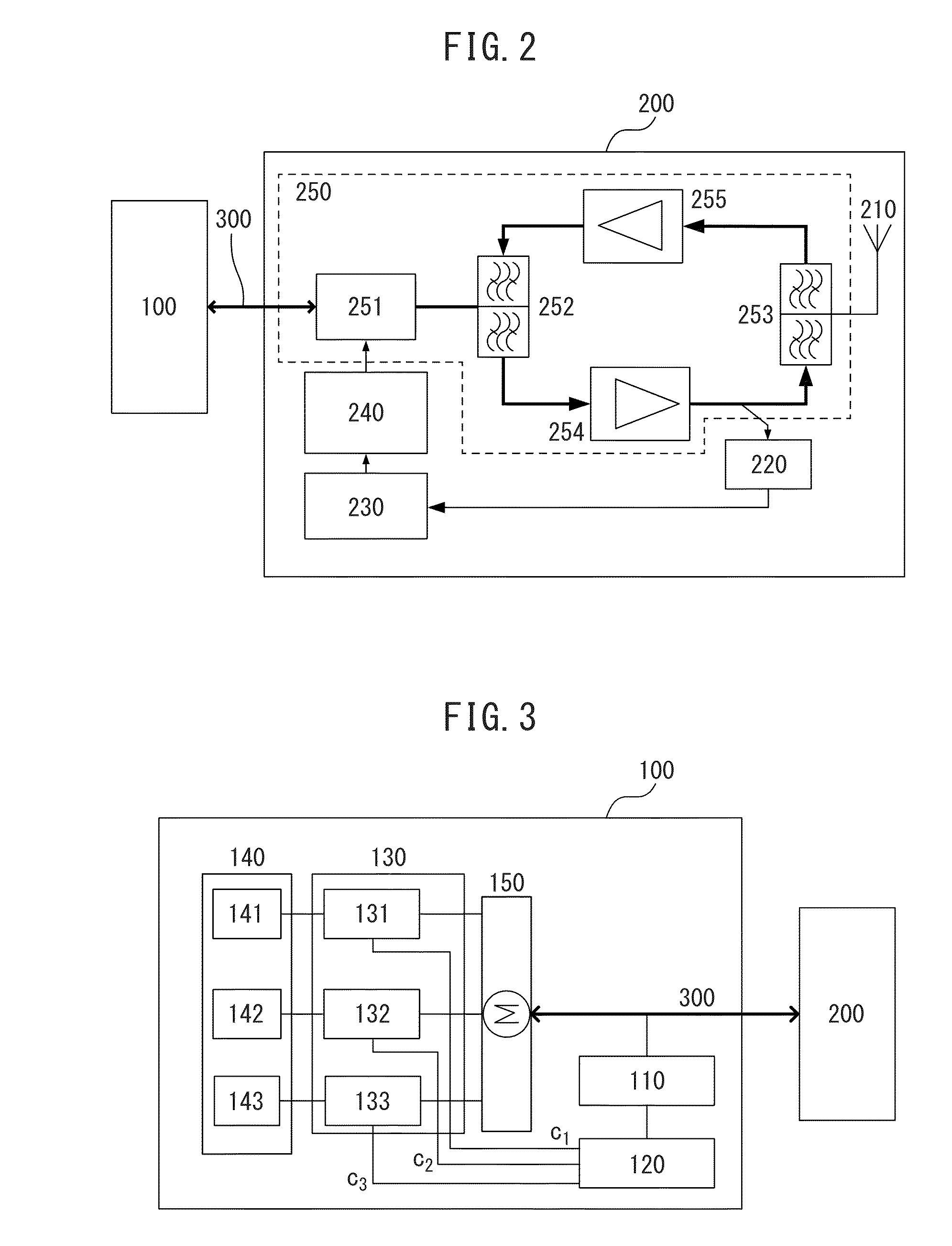
[0046]In the terms used in the present specification, a “direction from which a signal having a predetermined level or higher can be received” means a direction at which an evaluation result is equal to or greater than a threshold value of a specific signal quality when an evaluation result with respect to a signal quality in each direction is acquired by changing an orientation direction of the donor antenna according to an orientation angle c...


PUM


Abstract

An object of the present invention is to provide an antenna control system and a method capable of consistently maintaining an optimum orientation point between a donor antenna and an adjacent base station. The antenna control system for receiving a signal from a base station includes a donor antenna including an antenna module disposed by being fixed to an inner side of a window glass and configured with an array antenna; a phase shifter including a plurality of transmission lines; and a phase controller configured to control the phase shifter to change an orientation direction of the antenna module; and a repeater including a measuring module for measuring a reception signal received by the antenna module; an analyzing module for analyzing a signal quality parameter in each orientation direction of the antenna module based on a measurement result of the measuring module; and a generating module for generating an antenna control signal for controlling the orientation direction of the antenna module based on an analysis result of the analyzing module.

Description

BACKGROUND[0001]1. Technical Field[0002]The present invention relates to an antenna control method and the antenna control system.[0003]2. Description of the Related Art[0004]A mobile communication repeater is used to enable communication of a mobile communication telephone in a room where a mobile communication signal intensity is weak. The mobile communication repeater is a device which is installed in a place where a radio wave is weak or cannot reach between a base station and a terminal and supplies an excellent signal thereto to enable a stable wireless communication service.[0005]Generally, a donor antenna installed in an outdoor location, where an electric field intensity is high, supplies a signal received from the base station to the mobile communication repeater installed in a room, and the mobile communication repeater appropriately amplifies the signal and supplies the signal to an indoor antenna (Service Antenna).[0006]However, the donor antenna needs to be in a state ...

Claims


Application Information

Patent Timeline
IPC IPC(8): H01Q3/36H04B7/02H04B7/155H01Q9/04H01Q1/12
CPCH01Q1/1271H01Q3/36H01Q9/0407H04B7/026H01Q21/06H04W88/08H04W24/02H01Q1/005H01Q3/247H04B7/1555H04B7/10H04B7/14
Inventor TAJIKA, AKIHIKOMIYAKAWA, JUNICHISHIMAZAKI, YOSHIHITOLEE, HAEWOONLEE, CHEOLHOON
Owner HIWAVE
Why Eureka
Try Eureka