
Image processing device, imaging device, program, and image processing method

Active Publication Date: 2015-12-31
FUJIFILM CORP
View PDF27 Cites 18 Cited by
  • Summary
  • Abstract
  • Description
  • Claims
  • Application Information

AI Technical Summary

Benefits of technology

The invention is an image processing device with a touch panel that can adjust the focal position of a focus lens while obtaining the sense of directly operating a split image. This makes it easier for users to control the focus and composition of the display image. Additionally, the device can prevent difficulty in seeing a split image by stopping the control for reducing the display image when the size of the display image is equal to the size before enlarging it.

Problems solved by technology

However, in the manual focus mode, the operation is more complicated than that when focusing control is automatically performed (so-called automatic focus mode).
In particular, when the user is unaccustomed to an operation in the manual focus mode, it is difficult for the user to understand an operation method.
Therefore, when the focus is adjusted using the split image, the user is likely to feel that the operation of designating the focus detection region and adjusting the position of the focus lens is unnatural.
Even when the technique is simply applied to the techniques disclosed in JP2009-237214A and JP2011-151728A, the user is likely to feel that the operation of adjusting the position of the focus lens is unnatural.

Method used


Image

  • Image processing device, imaging device, program, and image processing method
  • Image processing device, imaging device, program, and image processing method
  • Image processing device, imaging device, program, and image processing method

Examples


first embodiment

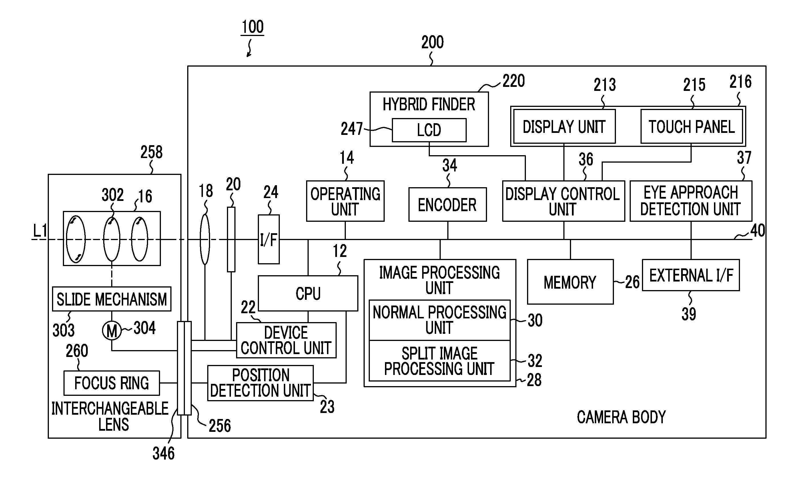
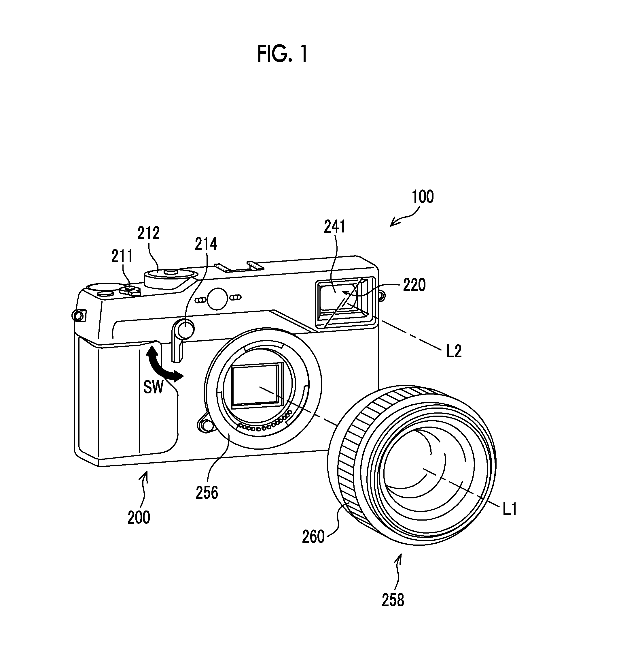
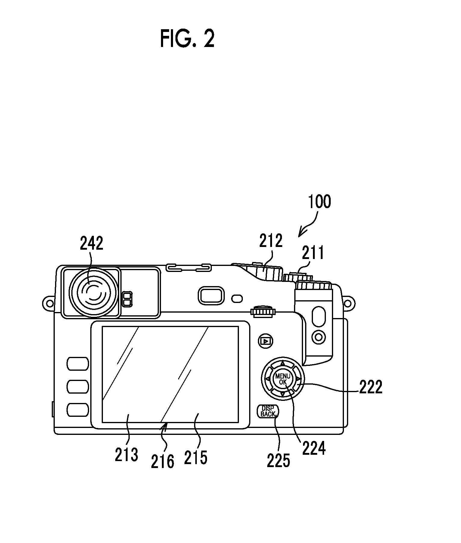
[0108]An imaging device 100 according to this embodiment is an interchangeable lens camera. As illustrated in FIG. 1, the imaging device 100 is a digital camera that includes a camera body 200 and an interchangeable lens 258, which is a zoom lens interchangeably mounted on the camera body 200, and does not include a reflex mirror. The interchangeable lens 258 includes an imaging lens 16 having a focus lens 302 that can be moved in an optical axis direction, a focus ring 260, a slide mechanism 303, and a motor 304 (see FIG. 3 which will be described in detail below). In addition, a hybrid finder (registered trademark) 220 is provided in the camera body 200. The hybrid finder 220 means, for example, a finder in which an optical viewfinder (hereinafter, referred to as an “OVF”) and an electronic viewfinder (hereinafter, referred to as an “EVF”) are selectively used.

[0109]A mount 256 provided in the camera body 200 and a mount 346 (see FIG. 3) which is provided in the interchangeable le...

second embodiment

[0318]In the first embodiment, in the scroll process, the designated position is moved in the direction of the parallax (horizontal direction) between the right eye image and the left eye image of the split image. However, the moving direction is not limited thereto. In this embodiment, a case in which an operation (circular motion) of moving the designated position in a circle as a modification of the moving direction is performed will be described in detail with reference to the drawings.

[0319]Since this embodiment has the same structure and operation as the first embodiment, the detailed description of the same structure and operation will not be repeated.

[0320]An imaging control process according to this embodiment differs from the imaging control process (see FIG. 1) according to the first embodiment in that a scroll process illustrated in FIG. 35 is performed instead of the scroll process in Step S415 (see FIG. 12). FIG. 35 is a flowchart illustrating the flow of the process o...

third embodiment

[0364]The imaging control process according to each of the above-described embodiments may be combined with other processes for focusing using the split image. In this embodiment, other processes which are preferably combined with the imaging control process according to each of the above-described embodiments will be described in detail with reference to the drawings.

[0365]In this embodiment, a focus informing process which informs the user that an image has been in focus will be described. FIG. 41 is a block diagram illustrating an example of the structure of an electrical system of an imaging device 100 according to this embodiment. As illustrated in FIG. 41, the imaging device 100 according to this embodiment includes an informing control unit 38 and a vibrating member 217 which inform the user that an image has been in focus, in addition to the structure of the imaging device 100 according to each of the above-described embodiments.

[0366]The informing control unit 38 is connect...


PUM


Abstract

Provided are an image processing device, an imaging device, and an image processing method which can perform focusing control using an intuitive operation. First and second images based on image signals that are output from an imaging element including first and second pixel groups on which an object image that passes through first and second regions of an imaging lens and is pupil-divided is formed are combined and displayed on a display unit having a touch panel. It is detected whether an operation of selecting the first or the second image on the display image is performed. It is detected whether a moving operation in a direction intersecting a division direction is performed. When the selection operation and the moving operation are sequentially detected, control is performed such that a focus lens is moved in an optical axis direction of the focus lens in response to the moving operation.

Description

CROSS-REFERENCE TO RELATED APPLICATIONS[0001]This application is a Continuation of PCT International Application No. PCT / JP2014 / 058407 filed on Mar. 26, 2014, which claims priority under 35 U.S.C. §119(a) to Japanese Patent Application No. 2013-074278 filed on Mar. 29, 2013 and Japanese Patent Application No. 2013-174876 filed on Aug. 26, 2013. Each of the above application(s) is hereby expressly incorporated by reference, in its entirety, into the present application.BACKGROUND OF THE INVENTION[0002]1. Field of the Invention[0003]The present invention relates to an image processing device, an imaging device, a program, and an image processing method, and more particularly, to an image processing device, an imaging device, a program, and an image processing method which generate an image for checking the focus state of an object image and display the image.[0004]2. Description of the Related Art[0005]In recent years, a technique has been used which displays a split image in a live v...

Claims


Application Information

Patent Timeline
IPC IPC(8): H04N5/232G02B7/34
CPCH04N5/23293H04N5/3696G02B7/34H04N5/23212H04N5/23216H04N5/23222H04N9/045H04N23/672H04N23/62H04N23/631H04N25/704H04N23/843H04N25/134H04N23/64
Inventor KAWAI, TOMOYUKIHAYASHI, JUNJIIZAWA, KATSUTOSHI
Owner FUJIFILM CORP
Learn More