Mobile robot

a robot and mobile technology, applied in the field of mobile robots, can solve problems such as robots being stuck or ‘beached'

Inactive Publication Date: 2016-01-07
DYSON TECH LTD
View PDF0 Cites 39 Cited by
  • Summary
  • Abstract
  • Description
  • Claims
  • Application Information

AI Technical Summary

Benefits of technology

[0013]In order to provide its biasing force in a balanced position, the swing arm may be located on a rear portion of the body aligned on a longitudinal axis of the body. A further option

Problems solved by technology

However, the rearward bias of its mass can cause the robot to become stuck or ‘beached’ if its m

Method used


Image

  • Mobile robot
  • Mobile robot
  • Mobile robot

Examples


Embodiment Construction

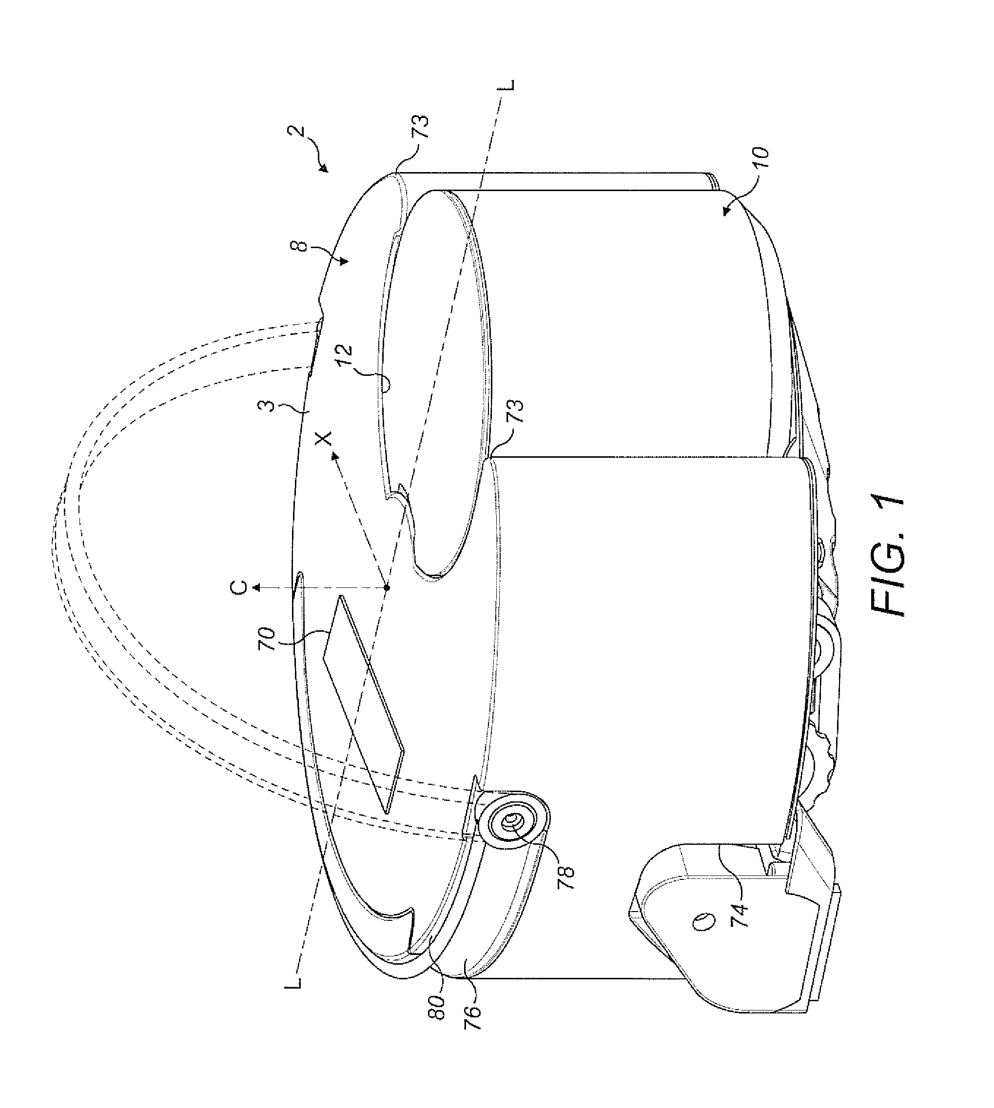
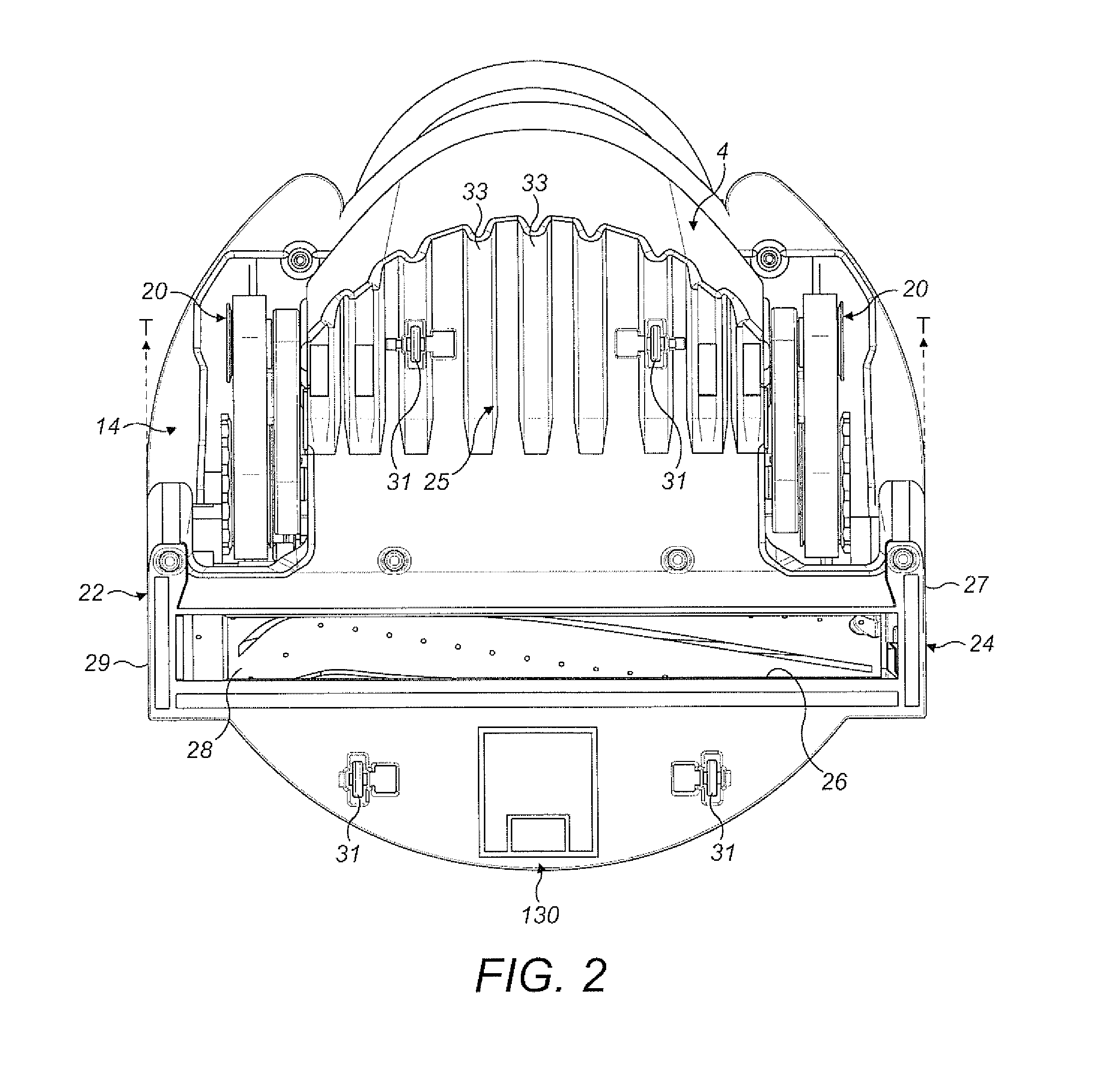
[0027]With reference to FIGS. 1, 2, 3 and 4 of the drawings, an autonomous surface treating appliance, in the form of a mobile robotic vacuum cleaner 2 (hereinafter ‘robot’) comprises a main body 3 having four principal assemblies: a chassis (or sole plate) 4, a body 6 which is carried on the chassis 4, a generally circular outer cover 8 which is mountable on the chassis 4 and provides the robot 2 with a generally circular profile, and a separating apparatus 10 that is carried on a forward part of the body 6 and which protrudes through a complementary shaped cut-out 12 of the outer cover 8.

[0028]For the purposes of this specification, the terms ‘front’ and ‘rear’ in the context of the robot will be used in the sense of its forward and reverse directions during operation, with the separating apparatus 10 being positioned at the front of the robot. Similarly, the terms ‘left’ and ‘right’ will be used with reference to the direction of forward movement of the robot. As will be apprecia...


PUM


Abstract

A mobile robot including a body having a drive arrangement for driving the body on a surface, the body further including a bias for biasing a rear portion of the body in a direction away from the floor surface. The bias may include a spring-loaded swing arm located on a rear portion of the body and which is movable between stowed and deployed positions.

Description

REFERENCE TO RELATED APPLICATIONS[0001]This application is a national stage application under 35 USC 371 of International Application No. PCT / GB2014 / 050214, filed Jan. 28, 2014, which claims the priority of United Kingdom Application No. 1301578.9, filed Jan. 29, 2013, the entire contents of which are incorporated herein by reference.FIELD OF THE INVENTION[0002]The invention relates to a mobile robot. In particular, although not exclusively, the invention has utility in the context of domestic mobile robot applications such as robotic floor sweepers, vacuum cleaners, and floor washers that are used in a home or office environment, for example.BACKGROUND OF THE INVENTION[0003]It is becoming increasingly common to see mobile robotic appliances around the home or office environment. Typically these robotic appliances are in the form of robotic floor sweepers or vacuum cleaners. Examples of known robotic vacuum cleaners are the Roomba™ range of machines manufactured by iRobot Corporatio...

Claims


Application Information

Patent Timeline
IPC IPC(8): A47L9/00A47L11/40
CPCA47L9/009A47L11/4061A47L2201/04A47L11/4072A47L11/4066A47L2201/00A47L9/00A47L11/40
Inventor VANDERSTEGEN-DRAKE, MARK STAMFORDROLLO, ADAM WILLIAM
Owner DYSON TECH LTD
Why Eureka
Try Eureka