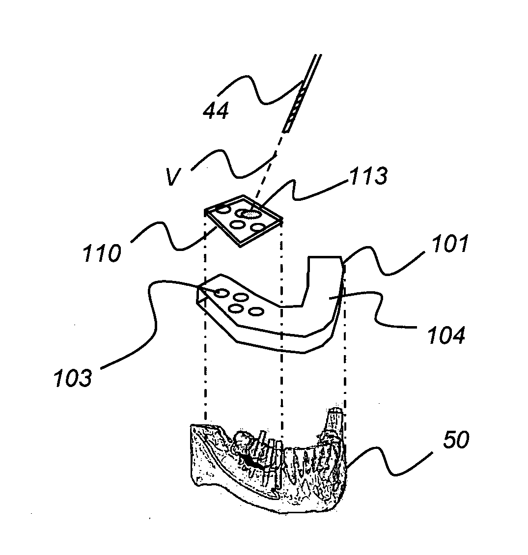
Partial surgical guide
a surgical guide and partial technology, applied in the field of surgical guide, can solve the problems of limitation to the suitable 4-axis device for forming surgical guide, and achieve the effect of being convenient to us
- Summary
- Abstract
- Description
- Claims
- Application Information
AI Technical Summary
Benefits of technology
Problems solved by technology
Method used
Image

Examples
Embodiment Construction
[0029]The following is a detailed description of preferred embodiments of the invention, reference being made to the drawings in which the same reference numerals identify the same elements of structure in each of the several figures. Similar descriptions concerning components and arrangement or interaction of components already described are omitted. Where they are used, the terms “first”, “second”, and so on, do not necessarily denote any ordinal or priority relation, but are simply used to more clearly distinguish one element from another.
[0030]In the context of the present disclosure, two features, such as lines or surfaces, are considered to be substantially orthogonal or perpendicular if the angle between them differs by less than about 3 degrees from an odd integer multiple of 90 degrees (for example, 90 degrees or 270 degrees). Two features are considered to be parallel, or substantially parallel, if the angle between them differs by less than about 3 degrees from an integer...
PUM
| Property | Measurement | Unit |
|---|---|---|
| angle | aaaaa | aaaaa |
| angle | aaaaa | aaaaa |
| angle | aaaaa | aaaaa |
Abstract
Description
Claims
Application Information