Automated track inspection system

a track inspection and automatic technology, applied in the direction of locomotive transmission, instruments, roads, etc., can solve the problems of replicating the load of a train, the inability of sensors to measure gauge, and the rolling of the rails, so as to reduce the interruption of revenue rail operations, avoid risks, and increase the frequency of loaded gauge measurements

Active Publication Date: 2016-01-07
RAILPOD
View PDF10 Cites 41 Cited by
  • Summary
  • Abstract
  • Description
  • Claims
  • Application Information

AI Technical Summary

Benefits of technology

[0014]Disclosed herein is a vehicle which deploys a track loading device referred to as an automatic track loading fixture (“ATLF”) to replicate the lateral load of a railcar or locomotive while providing geometry measurement inspection methods, identifying common track obstructions that would interfere with the proper placement of the ATLF, and obviating the need for specialized track geometry cars that require human operation. This readily increases the frequency of loaded gauge measurements, avoids risks to humans who would otherwise be physically operating the specialized track geometry vehicle or utilizing the PTLF, and reduces interruption of revenue rail operations.

Problems solved by technology

Unloaded measurements do not account for the weight of the locomotive or rail cars that physically spread the railroad gauge, cause rolling of the rails, and other geometric phenomenon when a load is applied.
However, because rail cars and locomotives typically are stored in rail yards for days at a time to load and unload goods, the associated sensors may be unavailable to measure gauge on a daily basis unless substantially every rail car and locomotive is equipped with such gauge measurement sensors.
Replicating the load of a train, however, is a costly effort that typically requires specialized equipment to efficiently collect these measurements in a short time period to minimize impact to revenue generating train operations.
As a manual device, the PTLF is designed to conduct point measurements since it would be cost and time prohibitive to attempt manual measurement of loaded track geometry across an entire network of railroad infrastructure using a PTLF device on a regular basis.
These specialized track geometry cars are relatively expensive to operate because a human is required to drive the vehicle along the rails, while an additional individual monitors the geometry measurements.
These specialized vehicles may impose scheduling constraints on revenue train operations that may result in infrequent deployment.
Additionally, split-axle systems have a tendency to result in a derailments due to the large lateral forces applied at the head of the rail causing delays in both inspection processes as well as revenue operations.
However, because rail cars travel across various rail networks and spend a portion of time in rail yards loading and unloading goods, the availability of the rail car and associated sensors are restricted to the schedule of that rail car.
The manual operation of the PTLF device, the limited frequency of a specialized track geometry vehicle, and the otherwise extensive deployment of geometry sensors on revenue trains may impede railroad operators from conducting loaded gauge measurements on a desired frequent day-to-day basis.

Method used


Image

  • Automated track inspection system
  • Automated track inspection system
  • Automated track inspection system

Examples


Embodiment Construction

[0031]In the following detailed description, reference is made to the accompanying drawings which form a part hereof, and in which are shown, by way of illustration, specific embodiments which may be practiced. It is to be understood that other embodiments may be used, and structural changes may be made without departing from the scope of this disclosure.

Operation

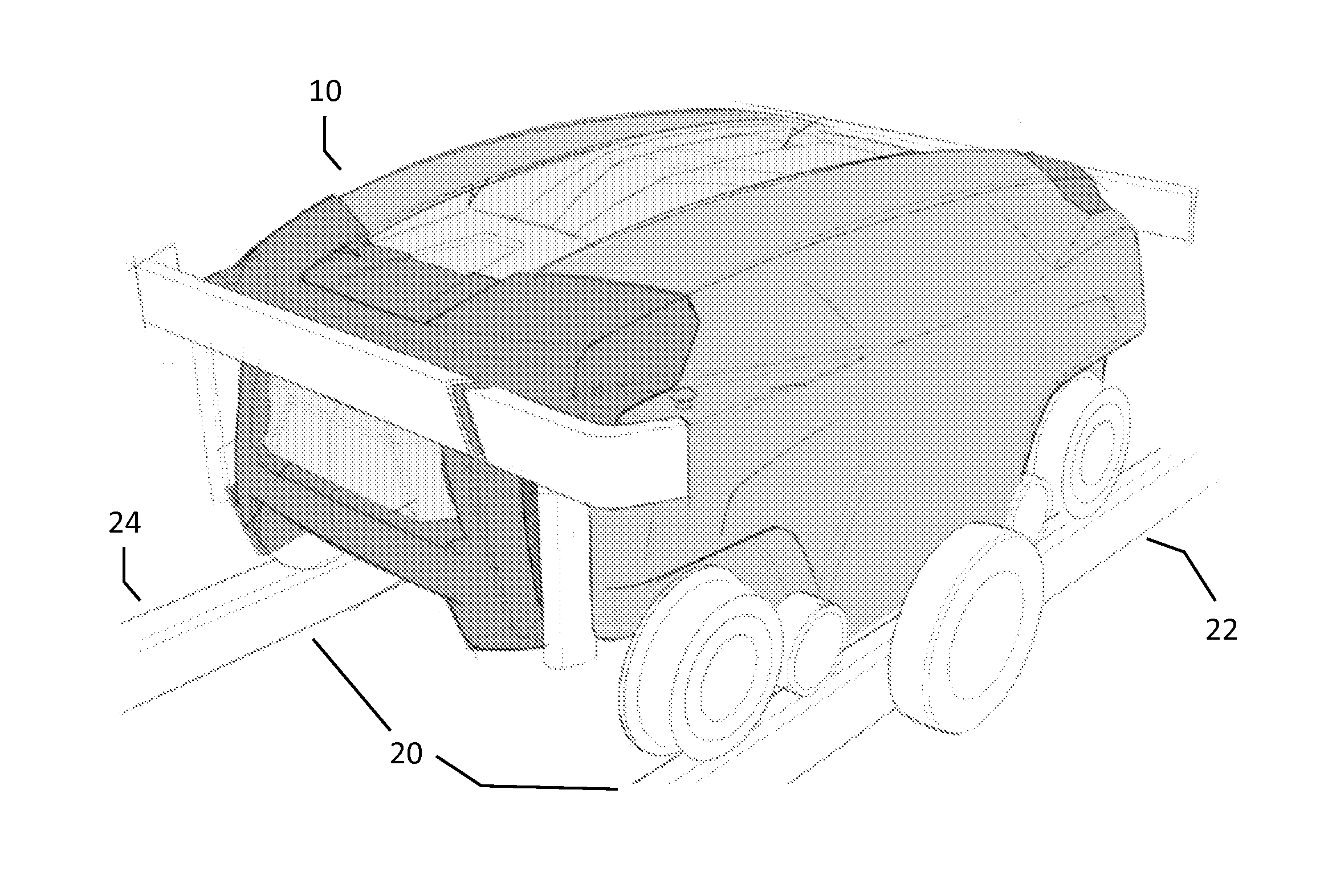
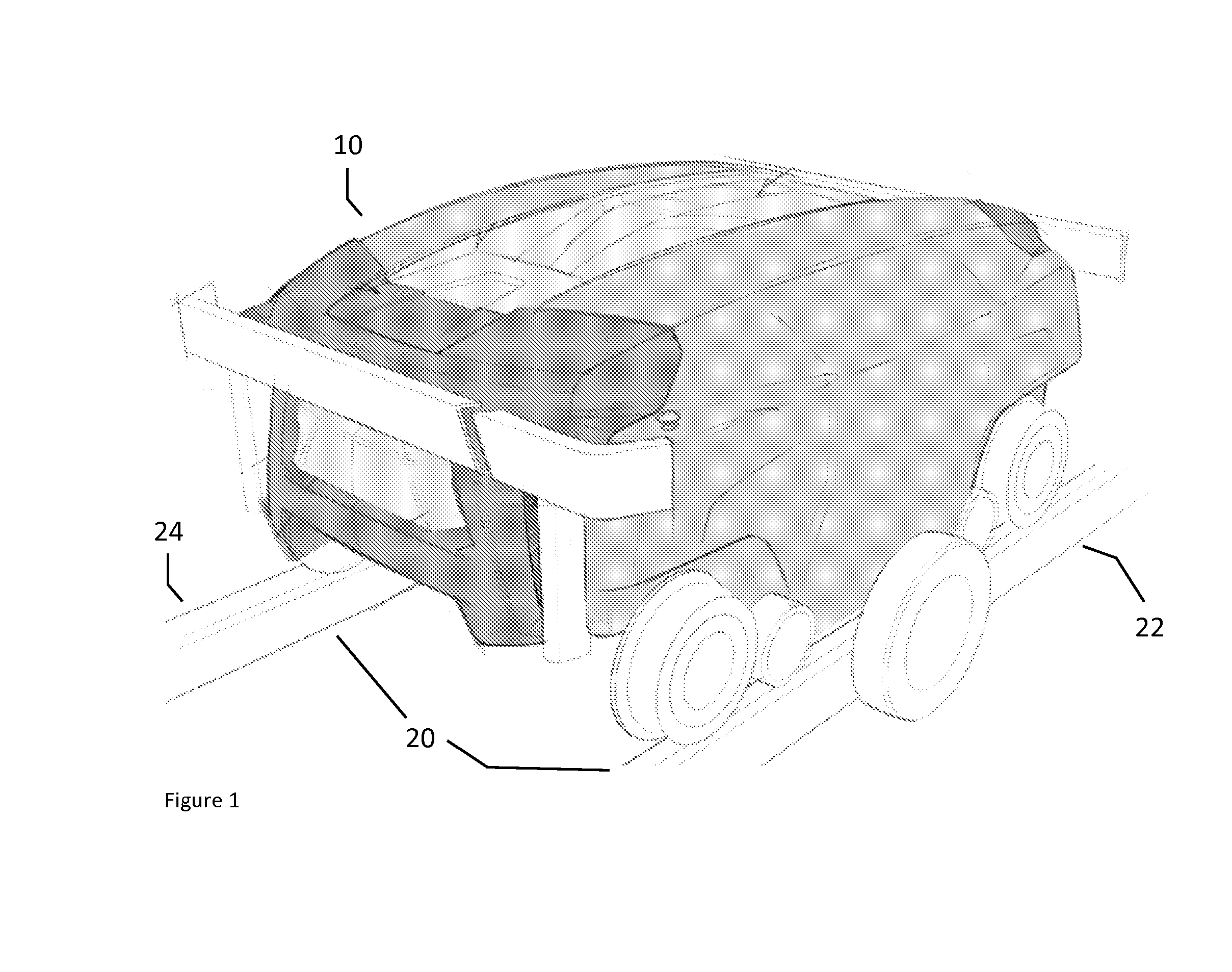
[0032]Referring to FIG. 1, vehicle 10 is configured for operation on conventional railroad track system 20. Conventional railroad track system 20 generally includes first rail 22 and second rail 24 supported in a spaced relationship. Vehicle 10, in this embodiment, is a robotic, self-propelled vehicle. Although depicted as a specific configuration, the concepts described herein are not limited to only such a configuration and the concepts and teachings may be applied to other configurations such as an outrigger configured vehicle, as well as various other vehicles such as robotic vehicles, hi-rail trucks, trains, cars, loco...


PUM


Abstract

An autonomous device for rail track inspection includes a drive wheel system propelling the device via a drive wheel system, an automatic track loading fixture for and applying a load on rails, and sensors for taking track gauge measurement. Different automatic track loading fixtures may require stopping for load and measurement, or loading and measuring while still in motion. A switch agnostic system for operation with devices on a conventional railroad track system includes a linear slider movably mounted along a linear sliding support; multiple sensors mounted to the linear slider, the sensors operable to identify a rail of a track junction; and multiple roller bearings operable to engage the rail of the track junction and control the device across the track junction in response to movement of the linear slider along the linear sliding support.

Description

CROSS-REFERENCE TO RELATED APPLICATIONS[0001]This utility patent application claims priority from U.S. provisional patent application Ser. No. 62 / 021,507, filed Jul. 7, 2014, titled “AUTOMATED TRACK INSPECTION SYSTEM” naming inventors Brendan English, Paul Sandin, Blair Morad, Shawn Dooley, and Craig Thrall, which is hereby fully incorporated by reference.COPYRIGHT NOTICE[0002]A portion of the disclosure of this patent document contains material that is subject to copyright protection. The copyright owner has no objection to the facsimile reproduction by anyone of the patent document or the patent disclosure, as it appears in the Patent and Trademark Office patent file or records, but otherwise reserves all copyright rights whatsoever. Copyright 2015, Rail Pod Incorporated.BACKGROUND[0003]1. Field of Technology[0004]The present disclosure relates generally to track inspection, and, more specifically, to an automated track inspection system operable to autonomously provide geometry m...

Claims


Application Information

Patent Timeline
Patent Type & Authority Applications(United States)
IPC IPC(8): E01B35/04
CPCE01B35/04B61K9/08
Inventor ENGLISH, BRENDANSANDIN, PAULMORAD, BLAIRDOOLEY, SHAWNTHRALL, CRAIG
Owner RAILPOD
Why Eureka
Try Eureka