Axially damped hydraulic mount assembly

a technology of hydraulic mounts and axial damped parts, which is applied in the direction of spring/damper functional characteristics, jet propulsion mounting, shock absorption, etc., can solve the problems of unsatisfactory vibration and some functional limitations of hydraulic mount types, and achieve the effect of increasing the functionality of the damper

Active Publication Date: 2016-01-07
CONTITECH USA INC
View PDF7 Cites 19 Cited by
  • Summary
  • Abstract
  • Description
  • Claims
  • Application Information

AI Technical Summary

Benefits of technology

[0015]A primary benefit of the disclosure relates to mounting through the center of the hydromount to significantly increase the functionality of the damper.
[0016]Another benefit resides in using the inertia track as a plunger that actuates fluids between the first and second fluid chambers to create a frequency dependent fluid effect damping.

Problems solved by technology

These high amplitude vibrations can be transferred from the origin of the excitation through a conventional mount to the side of the system where vibrations are not desirable.
However, these types of hydraulic mounts have some functional limitations because of the need to secure the hydraulic mount via the housing to the surrounding environment.

Method used


Image

  • Axially damped hydraulic mount assembly
  • Axially damped hydraulic mount assembly
  • Axially damped hydraulic mount assembly

Examples


Embodiment Construction

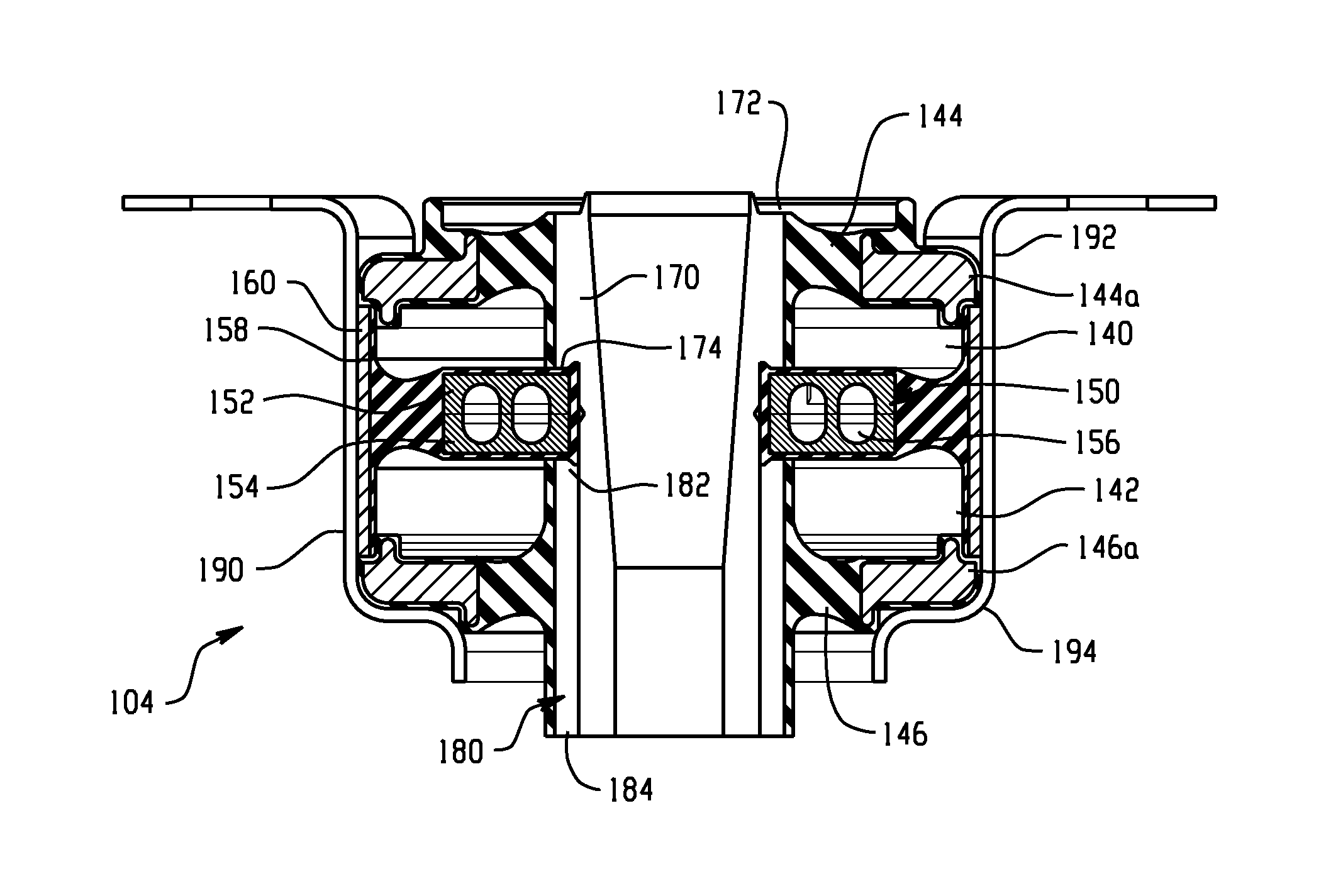
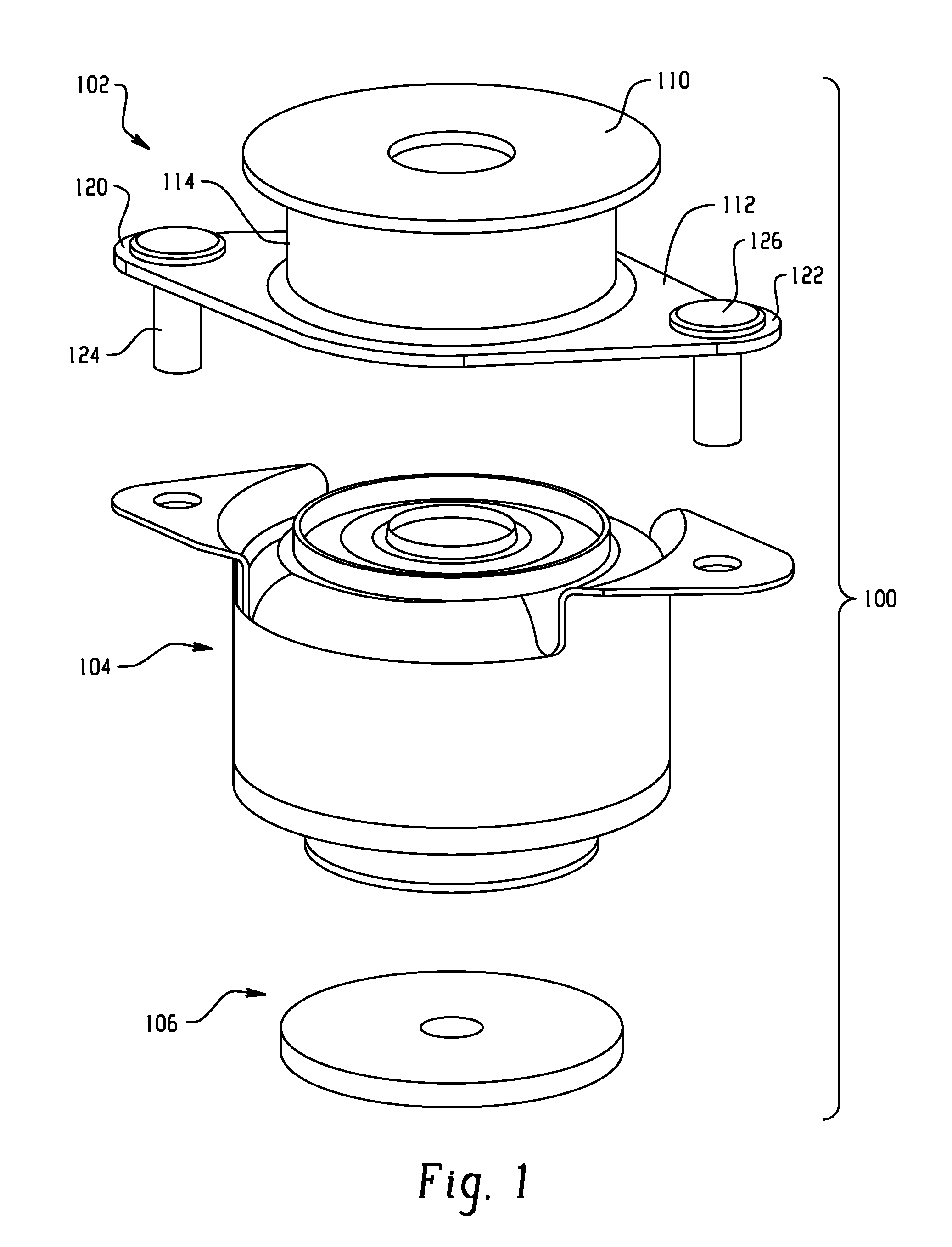
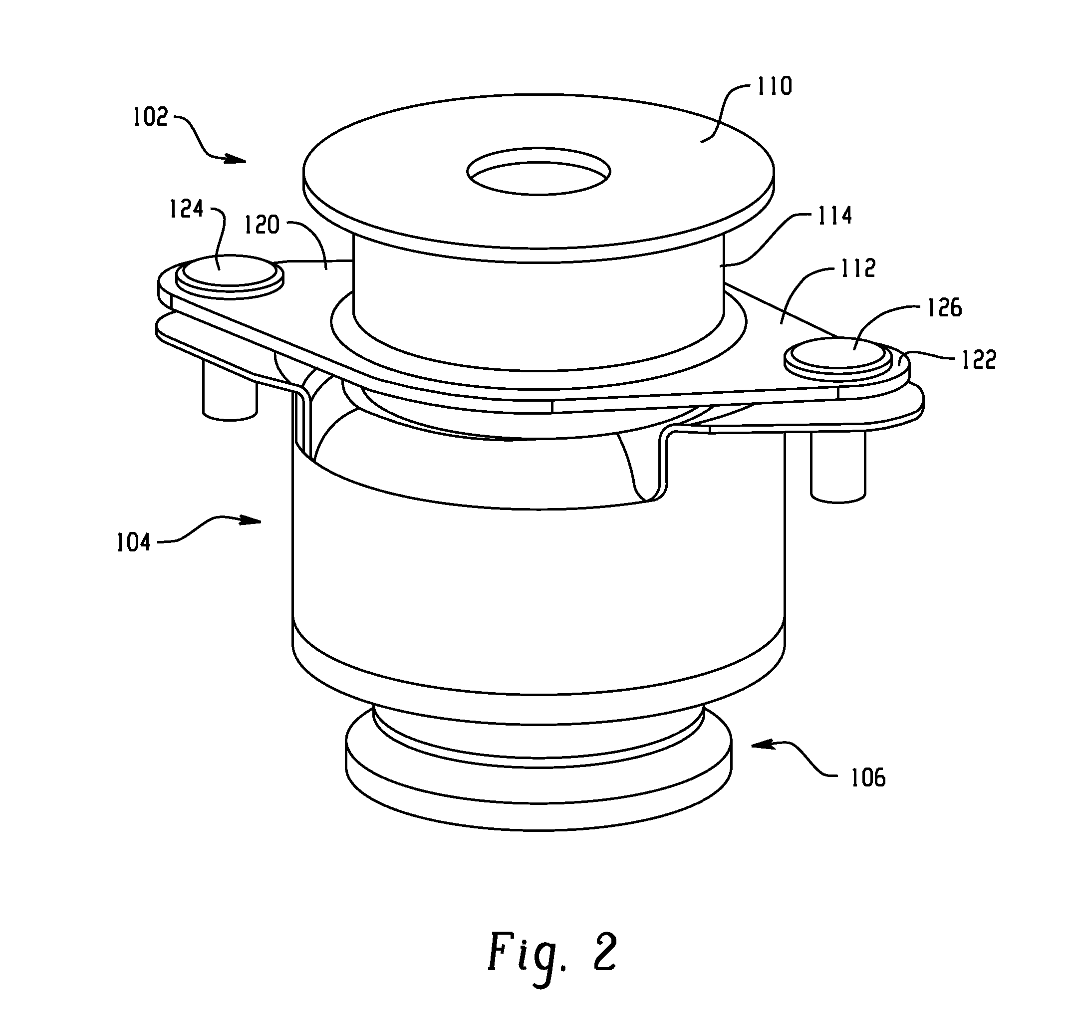
[0041]Turning first to FIGS. 1-3, a mount assembly or damper 100 is illustrated. A preferred embodiment of a mount assembly 100 includes a load bearing body mount 102, a hydraulic damper 104, and a travel restricting washer 106. The assembly 100 allows for a fastener such as a bolt (not shown) to pass through the center of the hydraulic damper, and in this case the body mount, while still creating damping in the axial direction. More particularly, the load bearing body mount 102 includes an upper, first component such as bearing plate 110 spaced from a lower, second component or mounting plate 112. The load bearing body mount further includes a damping member (sometimes referred to as a main rubber element or MRE) such as an elastomeric material or natural rubber 114 that is secured at opposite ends to the first component 110 and the second component 112, respectively. For example, the damping member may be mold bonded to the plates 110, 112 in a manner well know in the art. The mou...


PUM

PropertyMeasurementUnit
diameteraaaaaaaaaa
diameteraaaaaaaaaa
damping rateaaaaaaaaaa

Abstract

An example mount assembly includes an upper mount and a lower mount. The assembly also includes an inertia track having a central opening defining an axis. The inertia track defines a passage in fluid communication with the first chamber and the second chamber. The inertia track is moveable along the axis.

Description

REFERENCE TO RELATED APPLICATIONS[0001]This application is a continuation in part of U.S. application Ser. No. 14 / 719,916, filed May 22, 2015, which is a continuation of U.S. application Ser. No. 13 / 603,524, filed Sep. 5, 2012, which is a continuation-in-part of U.S. application Ser. No. 13 / 103,273 filed May 9, 2011, which is a continuation of U.S. application Ser. No. 12 / 865,602 filed Nov. 15, 2010 now U.S. Pat. No. 8,091,871, which is a National Phase application of PCT Application No. PCT / US2009 / 033199 filed Feb. 5, 2009, which claims priority to U.S. Provisional Application No. 61 / 026,291 filed Feb. 5, 2008.BACKGROUND OF THE DISCLOSURE[0002]This disclosure relates to a mount assembly or damper, and particularly a mount assembly that damps vibrations imposed on the assembly in a load bearing environment, including a fluid effect damping that is a combination of frequency dependent resonant damping and broadband viscous damping.[0003]Assemblies that damp vibrations and relative mo...

Claims


Application Information

Patent Timeline
Patent Type & Authority Applications(United States)
IPC IPC(8): F16F13/16B60K5/12F16F13/10
CPCF16F13/16F16F13/10F16F2228/06F16F2226/04B60K5/1208Y10T29/49615
Inventor BRADSHAW, JEFFERY MICHAELDOWSON, CHRISVALLIAPPAN, RAJRICE, BERNIE
Owner CONTITECH USA INC
Why Eureka
Try Eureka