Image forming apparatus

Inactive Publication Date: 2016-01-07
KONICA MINOLTA INC
View PDF0 Cites 4 Cited by
  • Summary
  • Abstract
  • Description
  • Claims
  • Application Information

AI Technical Summary

Benefits of technology

[0010]The first aspect of the present invention is an image forming apparatus having; an inside-air duct having a first inlet to an inside of the image forming apparatus; a first ventilator provided in the inside-air duct; an outside-air duct having a second inlet to an outside of the image forming apparatus; a common duct into which the inside-air duct and the outside-air duct are merged; a second ventilator provided in at leas

Problems solved by technology

However, in the case where the air from the inside and outside of the apparatus are expelled from the common outlet as in Japanese Patent L

Method used


Image

  • Image forming apparatus
  • Image forming apparatus
  • Image forming apparatus

Examples


first modification

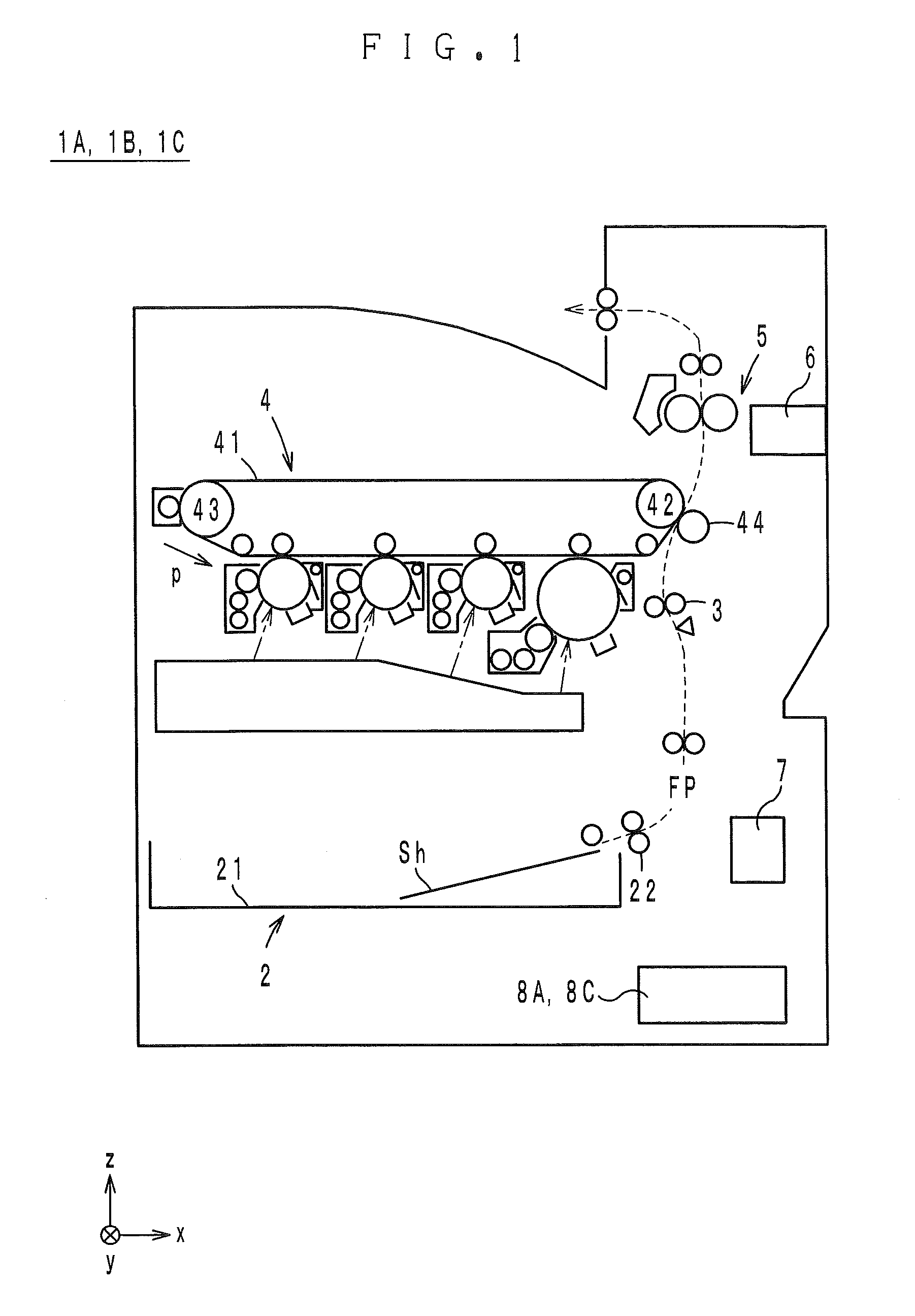
[0077]Next, an image forming apparatus 1B of the first modification is described. The image forming apparatus 1B has no difference in configuration from the above-described image forming apparatus 1A. Therefore, FIG. 1 to FIG. 5 are referred to for description of this modification. Components of the image forming apparatus 1B corresponding to those of the image forming apparatus 1A are designated by the same reference numerals, and the descriptions thereof are herein omitted.

Details of Control of Air Cleaner

[0078]Next, the control of an air cleaner 8B of this modification is described in detail with reference to FIG. 8A, FIG. 8B, and FIG. 9. FIG. 8A and FIG. 8B are different from the flowchart of FIG. 6 in that S201 to S205 are further included. FIG. 8A and FIG. 8B have no other difference from FIG. 6. Thus, steps in FIG. 8A and FIG. 8B corresponding to those of FIG. 6 are designated by the same step numbers, and the descriptions thereof are herein omitted.

[0079]Immediately after th...

second modification

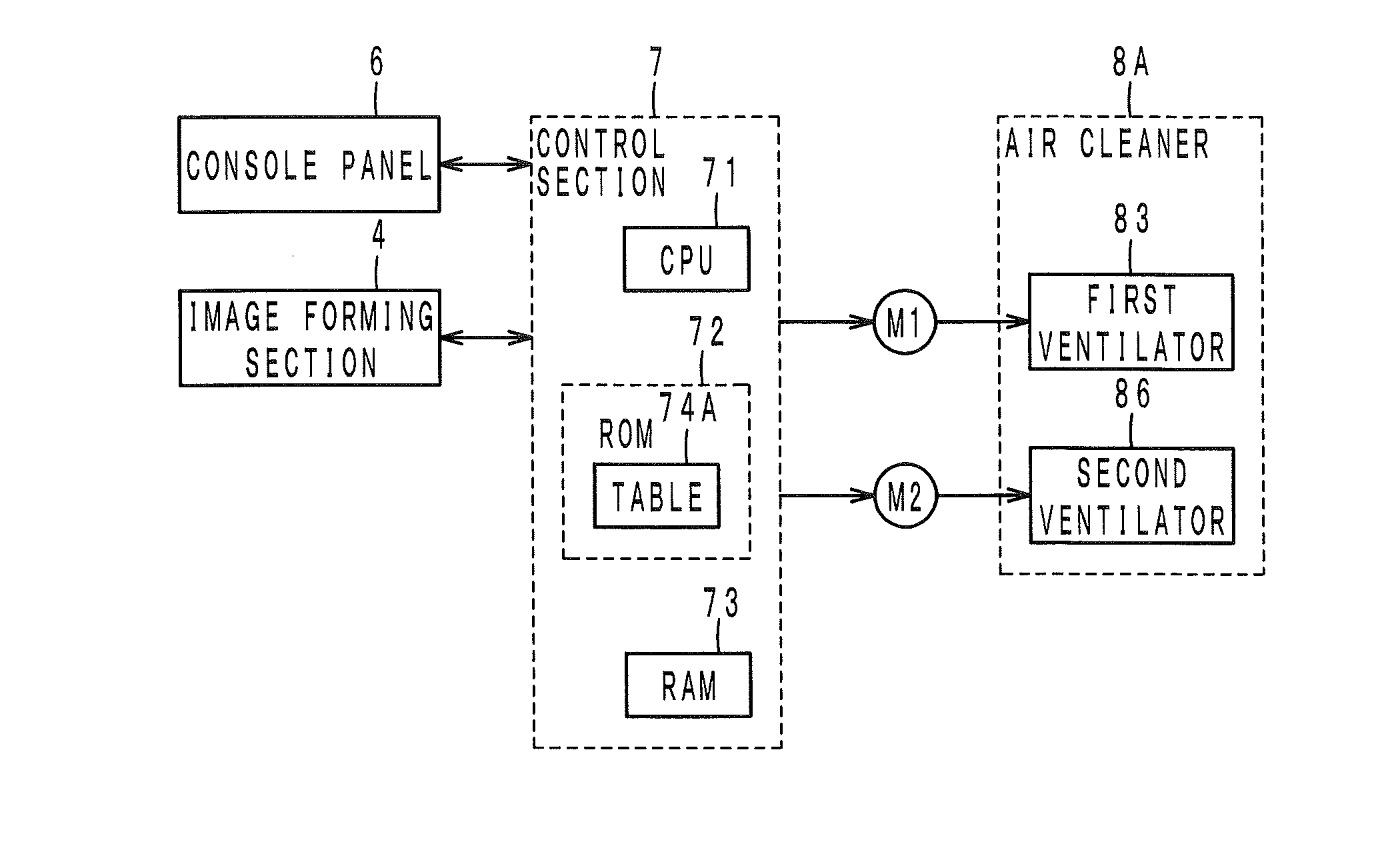
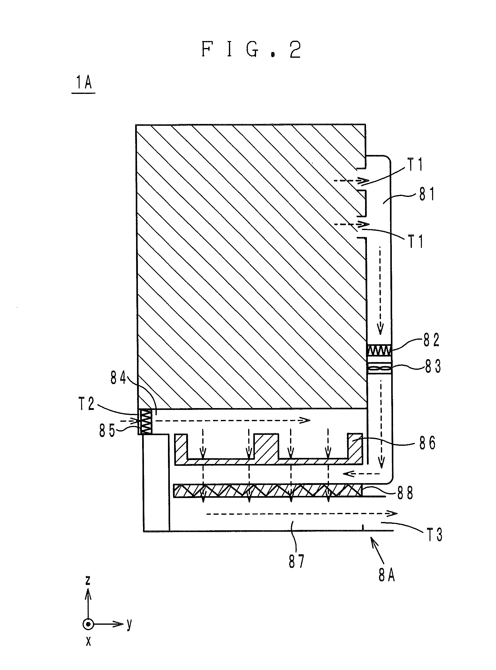
[0092]In the above-described embodiment, at S005 of FIG. 6, the CPU 71 sets the pressures P1, P2 based on the table 74A such that the target values of the flow rates Q1, Q2 are achieved. However, the present invention is not limited to this example. As shown in FIG. 10, for example, a first sensor 89 which is capable of outputting a signal indicative of the flow rate itself (or the variation of the flow rate), such as an air flow meter, barometer, or anemometer, may be provided immediately downstream of the first ventilator 83 in the inside-air duct 81, and a second sensor 810 which is the same type as the first sensor 89 may be provided immediately downstream of the outside-air filter 85 in the outside-air duct 84. In this case, the CPU 71 may exercise feedback control of the pressures P1, P2 of the ventilators 83, 86 based on the detection results of the sensors 89, 810 such that the target values of the flow rates Q1, Q2 are achieved.

third modification

[0093]In the above-described embodiment, the CPU 71 controls the pressure P2 based on the table 74A such that the variation of the flow rate Q2 is generally constant. However, the present invention is not limited to this example. As shown in FIG. 11, for example, a differential pressure gauge 811 may be provided immediately upstream and downstream of the outside-air filter 85 in the outside-air duct 84. In this case, the CPU 71 controls the pressure P2 such that the detection result of the differential pressure gauge 811 (i.e., the pressure difference between the upstream side and the downstream side) becomes generally 0.


PUM


Abstract

An image forming apparatus having: an inside-air duct having a first inlet to an inside of the image forming apparatus; a first ventilator provided in the inside-air duct; an outside-air duct having a second inlet to an outside of the image forming apparatus; a common duct into which the inside-air duct and the outside-air duct are merged; a second ventilator provided in at least one of the outside-air duct and the common duct; a filter provided in the common duct; and a control section that retrieves information indicative of an flow rate in the inside-air duct and increases a pressure produced by the second ventilator based on the retrieved information such that an flow rate in the outside-air duct is substantially constant with respect to an increase of the flow rate in the inside-air duct.

Description

[0001]This application is based on Japanese Patent Application No. 2014-135806 filed on Jul. 1, 2014, the content of which is incorporated herein by reference.BACKGROUND OF THE INVENTION[0002]1. Field of the Invention[0003]The present invention relates to an image forming apparatus including an air cleaner.[0004]2. Description of Related Art[0005]Common image forming apparatuses include an air cleaner for expelling air inside the apparatus to the outside. More specifically, in a fixing unit of the image forming apparatus, emissions such as an odor, volatile organic compounds (VOC), low molecular siloxane, dust (toners or paper dust), etc., are produced. The air cleaner includes a ventilator (typically, a fan) and a filter in an air passage. The ventilator is driven to collect air around the fixing unit. Emissions contained in the collected air are captured by the filter, and the cleaned air is expelled to the outside of the apparatus. Also, the image forming apparatus includes anoth...

Claims


Application Information

Patent Timeline
IPC IPC(8): G03G21/20
CPCG03G21/206G03G2221/1645
Inventor UMEMOTO, HIROAKITASHIRO, SHIGERUSATOU, MASAYUKIYAMAGUCHI, MASAHIROYOSHIKAWA, SHOICHI
Owner KONICA MINOLTA INC
Why Eureka
Try Eureka