Transmission apparatus, reception apparatus, and transmission and reception system

a technology which is applied in the field of reception apparatus and transmission apparatus, and the transmission and reception system, can solve the problems of difficult correct determination, difficult to optimize the pll circuit of the receiver, and the limitation of the operation band of the pll circuit, so as to improve the stability of communication during transmission

Active Publication Date: 2016-01-07
THE FUJIKURA CABLE WORKS LTD
View PDF7 Cites 8 Cited by
  • Summary
  • Abstract
  • Description
  • Claims
  • Application Information

AI Technical Summary

Benefits of technology

[0019]According to the present invention, it is possible to improve stability of communication during transmission and reception of data between a transmitter and a receiver.

Problems solved by technology

A PLL circuit typically has limitation on its operation band.
That is, it is difficult to correctly determine, from a state of a LOCK signal, whether or not the PLL circuit is properly operating.
However, there is a possibility that the PLL circuit of the receiver is not optimized like the PLL circuit of the transmitter.

Method used


Image

  • Transmission apparatus, reception apparatus, and transmission and reception system
  • Transmission apparatus, reception apparatus, and transmission and reception system
  • Transmission apparatus, reception apparatus, and transmission and reception system

Examples


embodiment 1

[0037]The following description will discuss Embodiment 1 of the present invention with reference to the drawings.

[0038][Configurations of Transmission Apparatus and Reception Apparatus]

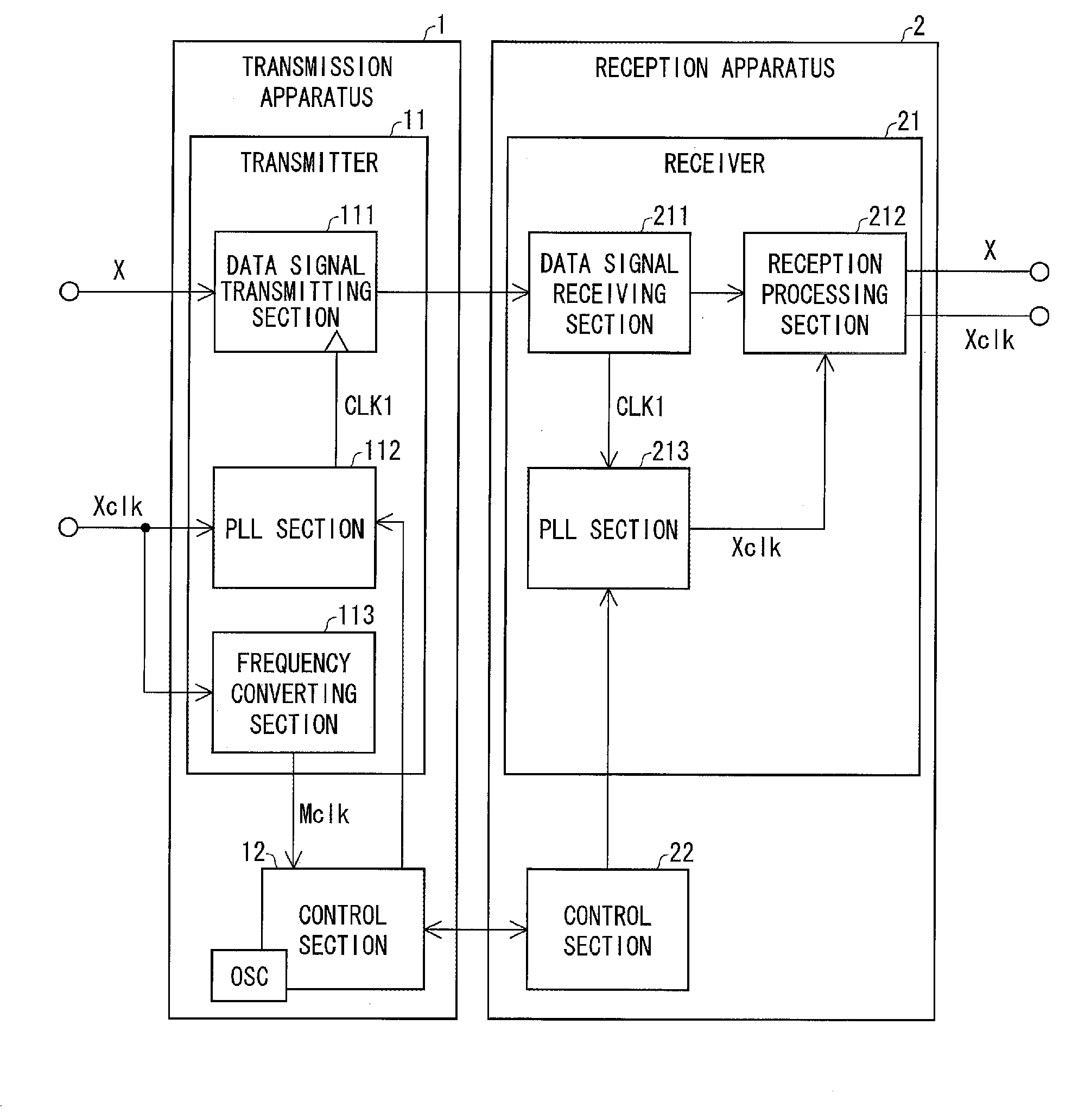
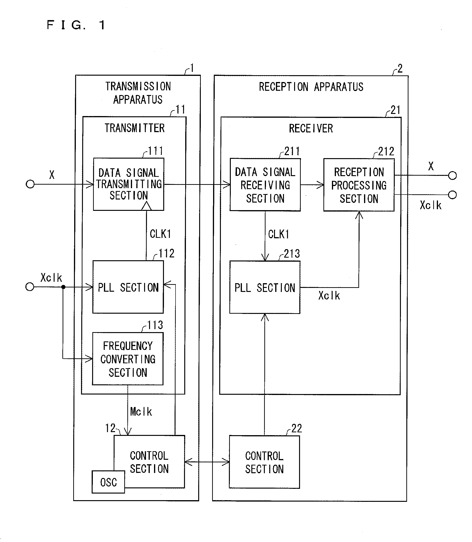
[0039]Configurations of a transmission apparatus 1 and a reception apparatus 2 of Embodiment 1 will be described with reference to FIG. 1. FIG. 1 is a block diagram illustrating configurations of sections of the transmission apparatus 1 and the reception apparatus 2. The transmission apparatus 1 is an apparatus configured to transmit a data signal X to the reception apparatus 2. The reception apparatus 2 is an apparatus configured to receive the data signal X from the transmission apparatus 1.

[0040]Note that the data signal X may be an electrical signal, an optical signal, a serial signal, or a parallel signal. For example, in a case where the transmission apparatus 1 is used as a camera-side connector in conformity to Camera Link, the data signal X is a parallel signal (data signals X0 through X3) t...

embodiment 2

[0108]The following description will discuss Embodiment 2 of the present invention with reference to drawings.

[0109][Configurations of Transmission Apparatus and Reception Apparatus]

[0110]Configurations of a transmission apparatus 1′ of and a reception apparatus 2′ of Embodiment 2 of the present invention will be described with reference to FIG. 9. FIG. 9 is a block diagram illustrating the configurations of the transmission apparatus 1′ and the reception apparatus 2′ of Embodiment 2.

[0111]The transmission apparatus 1′ is an apparatus configured to transmit a data signal X to the reception apparatus 2′. The transmission apparatus 1′ includes a transmitter 11, a control section 12, and a jitter removing section 13. The transmitter 11 and the control section 12 which are included by the transmission apparatus 1′ of Embodiment 2 are blocks whose respective functions identical to those of the transmitter 11 and the control section 12 which are included by the transmission apparatus 1 (p...

embodiment 3

[0145]The following description will discuss Embodiment 3 of the present invention with reference to drawings.

[0146][Configurations of Transmission Apparatus and Reception Apparatus]

[0147]Configurations of a transmission apparatus 1″ and a reception apparatus 2″ of Embodiment 3 of the present invention will be described with reference to FIG. 13. FIG. 13 is a block diagram illustrating the configurations of the transmission apparatus 1″ and the reception apparatus 2″ of Embodiment 3.

[0148]The transmission apparatus 1″ is an apparatus configured to transmit a data signal X to the reception apparatus 2″. The transmission apparatus 1″ includes a transmitter 11, a control section 12, and a jitter removing section 13. The transmitter 11 and the control section 12 which are included by the transmission apparatus 1″ of Embodiment 3 are blocks having respective functions identical to those of the transmitter 11 and the control section 12 which are included by the transmission apparatus 1 (p...


PUM


Abstract

A transmission apparatus transmits a data signal to a reception apparatus with use of a first clock generated on the basis of a clock signal given to the transmission apparatus. The transmission apparatus changes an operation band of a PLL section to an operation band including a frequency of the clock signal which frequency has been measured with use of a second clock independent of the first clock. The transmission apparatus provides the reception apparatus with band information indicative of the operation band to which the operation band of the PLL section has been changed.

Description

CROSS-REFERENCE TO RELATED APPLICATIONS[0001]This application is a Continuation of PCT International Application No. PCT / JP2014 / 061406 filed in Japan on Apr. 23, 2014, which claims the benefit of Patent Application No. 2013-095338 filed in Japan on Apr. 30, 2013, the entire contents of which are hereby incorporated by reference.TECHNICAL FIELD[0002]The present invention relates to (i) a transmission apparatus which transmits a data signal, (ii) a transmission method of transmitting a data signal, (iii) a reception apparatus which receives a data signal, (iv) a reception method of receiving a data signal, and (v) a transmission and reception system including the transmission apparatus and the reception apparatus.BACKGROUND ART[0003]A transmission and reception system for transmitting and receiving data signals often uses a clock signal to determine a transmission clock and a reception clock. In a transmission and reception system, such as Camera Link (Registered Trademark), in which ...

Claims


Application Information

Patent Timeline
Patent Type & Authority Applications(United States)
IPC IPC(8): H04L7/033H04L7/00H04L12/841
CPCH04L7/0331H04L7/0012H04L47/283H03L7/22H03L7/183H04L7/02H04N5/073H04N5/38H04L25/00
Inventor ARAI, YOSHINORI
Owner THE FUJIKURA CABLE WORKS LTD
Why Eureka
Try Eureka