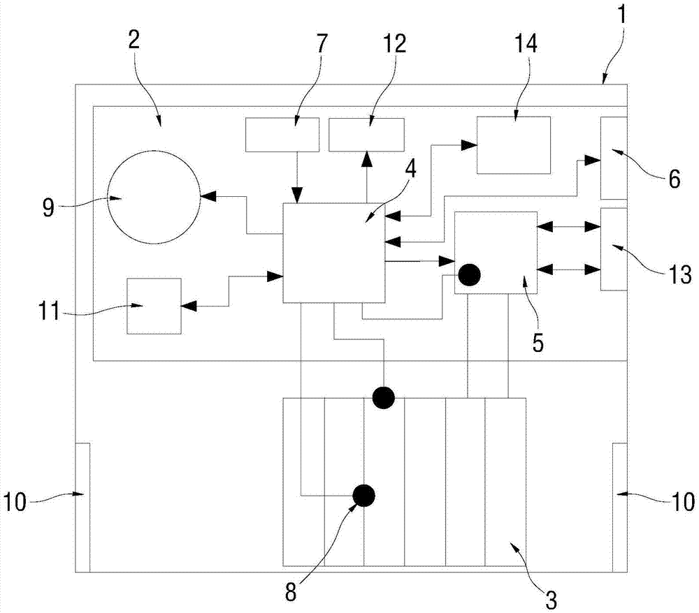
Intelligent battery used for unmanned aerial vehicle

A technology for smart batteries and drones, applied in secondary batteries, battery data exchange, battery circuit devices, etc., can solve problems such as affecting the life of components in the battery, small contact area, and inability to dissipate heat in a timely and effective manner. Achieve the effect of improving communication stability, ensuring safety and reliability, and avoiding unstable data transmission

Pending Publication Date: 2017-07-18
丰翼科技(深圳)有限公司
View PDF6 Cites 7 Cited by
  • Summary
  • Abstract
  • Description
  • Claims
  • Application Information

AI Technical Summary

Problems solved by technology

[0003] 1) The existing drone battery has a self-power supply system inside itself, but it cannot power off the management chip, that is, the management IC (integrated circuit). Therefore, when the program is abnormal, the management chip cannot reset itself , although a hardware or software watchdog can be added, but this is more likely to cause an external reset and cause abnormal operation;
[0004] 2) The current of the existing drone battery is very large when it is discharged. Oxide-Semiconductor Field-Effect Transistor (MOSFET for short) will generate a lot of heat. At the same time, when the battery is internally balanced and self-discharged, a large amount of heat will also be generated by a large resistor. Traditional battery casings are airtight and there is no heat dissipation device. , In this way, the heat generated by the battery operation cannot be dissipated in a timely and effective manner, which seriously affects the life of the components in the battery;
[0005] 3) The contact area of ​​the connector through which the large current passes is relatively large, and the plug-in resistance is better. However, the connector for external signal transmission in the existing drone battery often uses a smaller connector, and its contact The area is small, and it often needs to be plugged and unplugged many times during use. After multiple plugs and plugs, it is prone to poor contact, especially when used with a smart charger, this connector wears out faster

Method used


Image

  • Intelligent battery used for unmanned aerial vehicle

Examples


Embodiment Construction

[0024] In order to make the object, technical solution and advantages of the present invention clearer, the present invention will be further described in detail below in conjunction with the accompanying drawings and embodiments. It should be understood that the specific embodiments described here are only used to explain the present invention, not to limit the present invention.

[0025] It should be noted that when an element is referred to as being “fixed on” or “disposed on” another element, it may be directly on the other element or there may be an intervening element at the same time. When an element is referred to as being "connected to" another element, it can be directly connected to the other element or intervening elements may also be present.

[0026] In addition, it should be noted that the orientation terms such as left, right, up, and down in the embodiments of the present invention are only relative concepts or refer to the normal use state of the product, and...


PUM


Abstract

The invention relates to the unmanned aerial vehicle battery technology field, and discloses an intelligent battery used for an unmanned aerial vehicle. The intelligent battery comprises a housing, a battery management board detachably disposed in the housing, and an electric core group capable of realizing rapid charging. The battery management board is provided with a battery management unit used for the management of the battery, is connected with the MOS tube of the battery management unit, is connected with the power supply input/output interface of the MOS tube, and is connected with the CAN bus interface of the battery management unit. The CAN bus interface is connected with the main control system of the unmanned aerial vehicle for CAN bus communication. The electric core group is electrically connected with the MOS tube. The intelligent battery used for the unmanned aerial vehicle is advantageous in that by arranging the CAN bus interface, the CAN bus communication with the main control system of the unmanned aerial vehicle is realized, and a problem of instable data transmission between the intelligent battery and the main control system of the unmanned aerial vehicle is prevented, the stability of the communication is improved, and the safety and the reliability of the flight of the unmanned aerial vehicle are guaranteed.

Description

technical field [0001] The invention relates to the technical field of unmanned aerial vehicle batteries, in particular to an intelligent battery for unmanned aerial vehicles. Background technique [0002] The battery management of existing drones can realize functions such as power management, abnormal protection, and host computer communication. However, in actual use, the battery current output is very large, and the interference to the battery management board itself is also great, which often leads to abnormal communication data with the host computer, which leads to misjudgment of the battery status by the UAV, which in turn leads to unmanned The flight abnormality of the drone has seriously affected the flight safety of the drone. In addition, the batteries of existing drones also have the following problems: [0003] 1) The existing drone battery has a self-power supply system inside itself, but it cannot power off the management chip, that is, the management IC (i...

Claims


Application Information

Patent Timeline
Patent Type & Authority Applications(China)
IPC IPC(8): H02J7/00H01M10/48H01M10/613
CPCH02J7/0022H01M10/486H02J7/0047H02J7/0049H02J7/00034H01M10/4257Y02E60/10
Inventor 张浩陆再政冯俊龙姜明涛
Owner 丰翼科技(深圳)有限公司
Why Eureka
Try Eureka