
Wireless communication connection destination selecting method and device

Inactive Publication Date: 2008-06-19
FUJITSU LTD
View PDF10 Cites 6 Cited by
  • Summary
  • Abstract
  • Description
  • Claims
  • Application Information

AI Technical Summary

Benefits of technology

[0015]An object of the present invention is to provide a method and a device that enable the wireless terminal located within service areas of a plurality of base stations to select a base station having a highest quality when hand-over is performed or when it is activated.
[0018]In this way, the destination of hand-over or the connection destination when it is activated is determined. Therefore, the communication channel having the highest quality is selected when the wireless communication is actually performed. Thus, stability of communication is improved, and the number of processes for connection is reduced.
[0019]According to the present invention, in the wireless terminal that is within service areas of a plurality of base stations, it is possible to select a base station having the highest quality upon hand-over or when it is activated.

Problems solved by technology

However, this terminal is in the situation in which hand-over cannot be performed.
However, if a radius of the cell is large and a distance from the base station is small, i.e., even if possibility of hand-over is very low, the decision period becomes short if the moving speed of the terminal is high, so power consumption cannot be reduced.
However, cost of the system increases because installation of the server is necessary.

Method used


Image

  • Wireless communication connection destination selecting method and device
  • Wireless communication connection destination selecting method and device
  • Wireless communication connection destination selecting method and device

Examples


Embodiment Construction

[0024]The invention will now be described in detail with reference to the attached drawings.

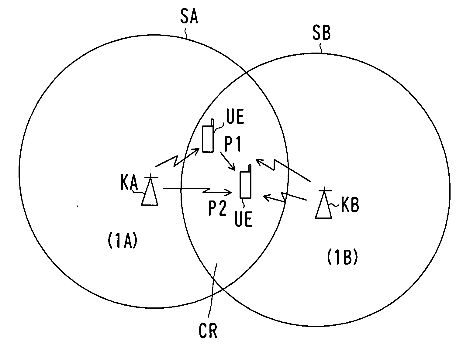
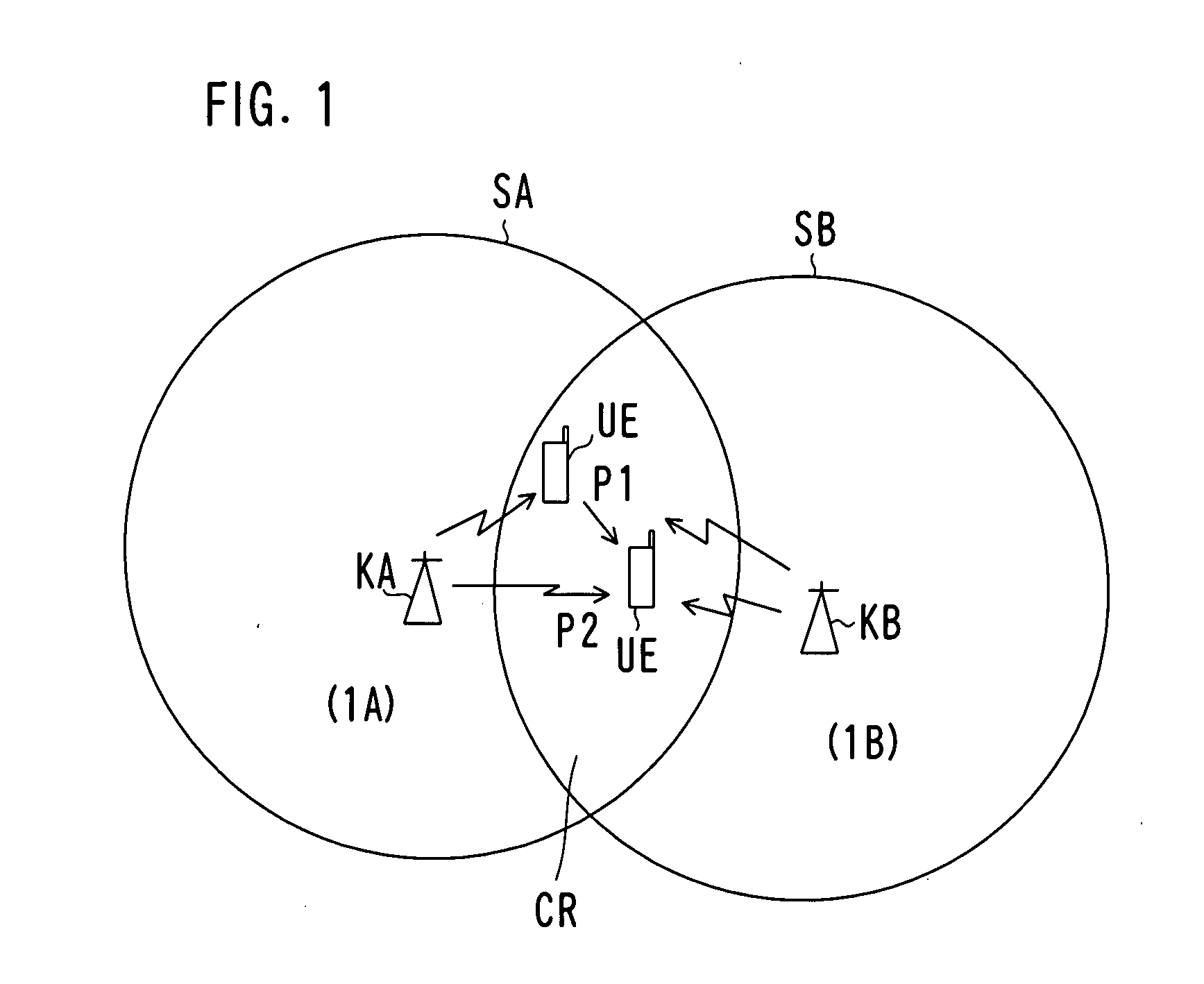
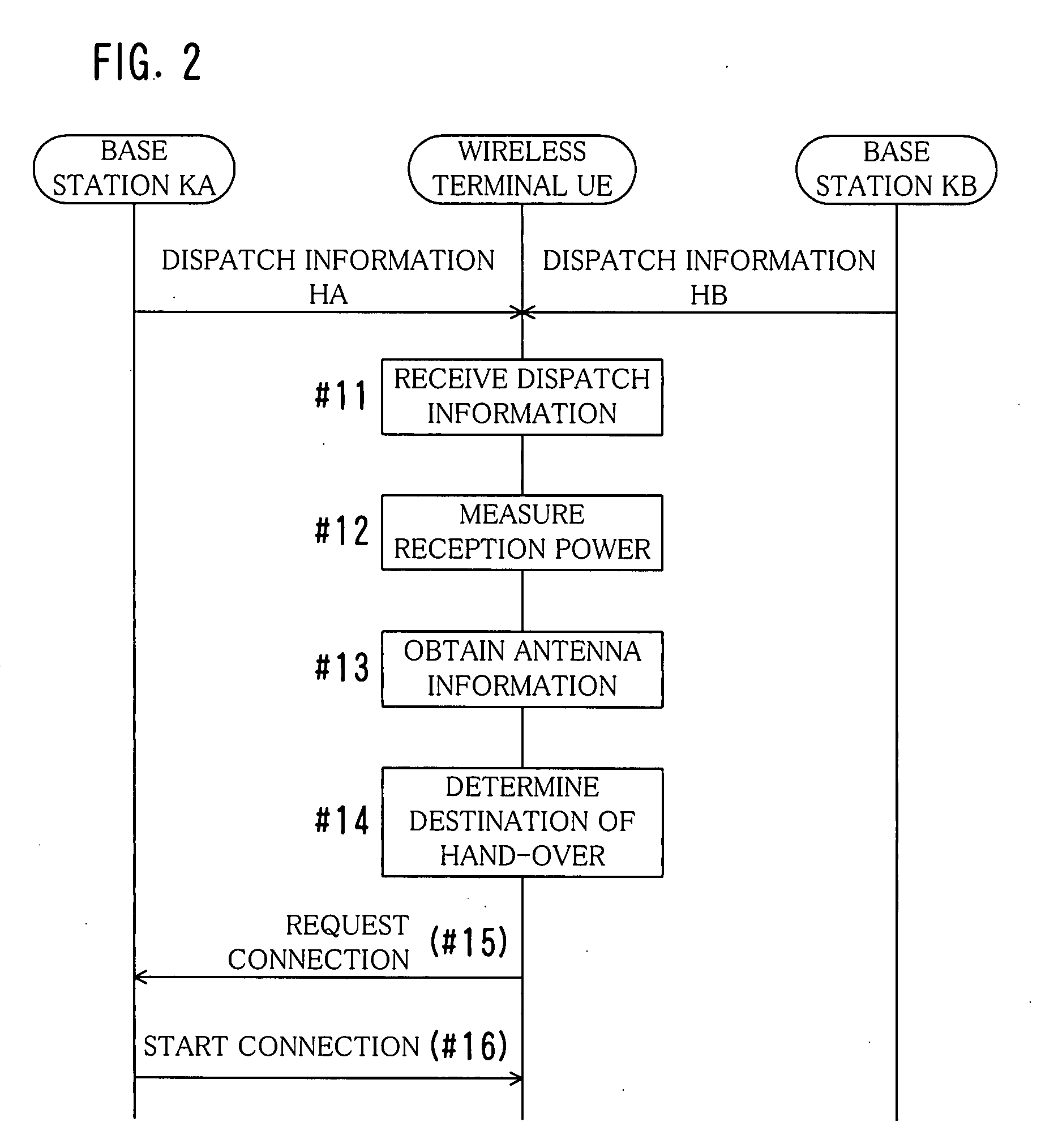
[0025]FIG. 1 is a diagram showing service areas of base stations for explaining a selecting method according to an embodiment of the present invention, FIG. 2 is a flowchart showing the selecting method according to an embodiment of the present invention, FIG. 3 is a block diagram showing a general structure of a wireless terminal, and FIG. 4 is a block diagram showing a functional structure of the wireless terminal according to an embodiment of the present invention.

[0026]In FIG. 1, two base stations KA and KB and their service areas SA and SB are shown. The base stations KA and KB may belong to the same wireless communication system 1 or to different wireless communication systems 1A and 1B. The service areas SA and SB are areas where a wireless terminal (mobile terminal) UE can receive dispatch information from the base stations KA and KB. They may match areas of cells of the base stations...


PUM


Abstract

A method for selecting a connection destination for wireless communication from a plurality of base stations in a wireless terminal that is in service areas of the plurality of base stations, which includes a first step (#11) of receiving dispatch information from each of the plurality of base stations, a second step (#12) of obtaining information about each reception power when the dispatch information is received, a third step (#13) of obtaining information about an antenna that is used by each of the base stations for wireless communication after connection from each of the received dispatch information, and a fourth step (#14) of selecting a base station having a highest quality of a communication channel in the wireless communication as the connection destination based on the information about the reception power and the information about the antenna of each of the base stations.

Description

BACKGROUND OF THE INVENTION[0001]1. Field of the Invention[0002]The present invention relates to a method and a device for selecting a connection destination for wireless communication from a plurality of base stations in a wireless terminal located within a service area of the plurality of base stations. In particular, the present invention relates to a method for selecting a base station so that hand-over can be performed smoothly in a mobile phone.[0003]2. Description of the Prior Art[0004]Recently, mobile communication using mobile phones or PHS phones has been widespread astonishingly. For the mobile communication, wireless terminals (mobile terminals) such as mobile phones, wireless base stations, base station controlling devices, exchanges and the like constitute a wireless communication system (a mobile communication system).[0005]Along with widespread mobile communication, services using various types of wireless communication systems such as PDC, GSM, W-CDMA, CDMA-2000, W-...

Claims


Application Information

Patent Timeline
IPC IPC(8): H04Q7/20H04W36/30H04W36/36
CPCH04W36/36H04W36/30H04W36/302H04W36/362H04W48/20
Inventor ISHIZU, EIZOUSHIBA, TAMIONAGANO, MANABU
Owner FUJITSU LTD
Learn More