Pressure casting apparatus and method

a technology of pressure casting and pressure casting, applied in the direction of slip casting moulds, ceramic shaping apparatus, manufacturing tools, etc., can solve the problems of compromising durability, compromising durability, and pressure casting machines that have not traditionally been equipped, so as to facilitate tighter and more even drainage, simplify and encourage demoulding, and improve the effect of flexibility

Inactive Publication Date: 2016-01-14
PCL CERAMICS
View PDF1 Cites 8 Cited by
  • Summary
  • Abstract
  • Description
  • Claims
  • Application Information

AI Technical Summary

Benefits of technology

[0011]The apparatus described in the foregoing paragraph provides a means of securing the following advantages:
[0035]Such fine tuning allows ultimately for the production of a better end-product.

Problems solved by technology

Clay is an anisotropic material consisting of plate-like particles, which tend to orientate themselves in the same way when clay is in the liquid phase; however, the mixture is thixotropic and this poses challenges to the effective joining of components of the mould as a first assembly of platelike particles blocks the merging flow path of a second set of such particles; this problem is known as “slip meet”; two parts of a mould are brought together and the platelike particles of the two separate flows meet, but do not mix.
Whilst it is quite possible for the user to adhere different moulded components of an article together, the user is nonetheless left with lines of weakness which can lead to cracking and aesthetic imperfection, as well as compromising durability.
Pressure casting machines have not traditionally been equipped so as to control the flow of slurry in this manner.
First, the slip does not drain evenly, creating an uneven cast.
Second, the presence of the button hole itself, even when filled, weakens the structure of the bowl.
Third the process of creating and fitting button holes to bowls is time consuming and adds extra steps and therefore builds extra complexity into the bowl production process.

Method used


Image

  • Pressure casting apparatus and method
  • Pressure casting apparatus and method
  • Pressure casting apparatus and method

Examples


Embodiment Construction

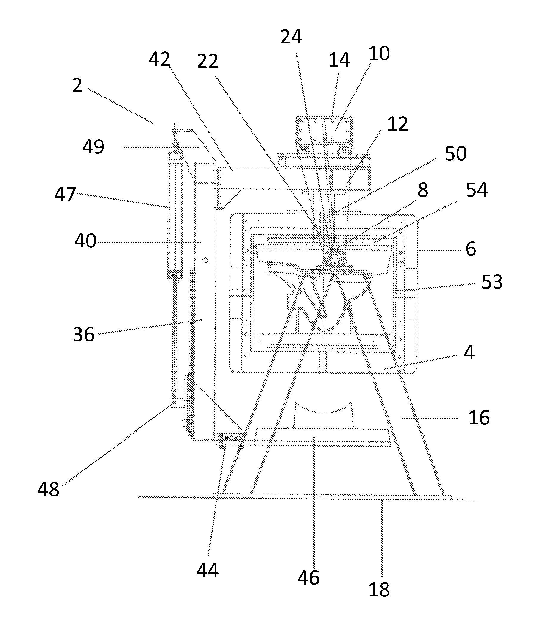
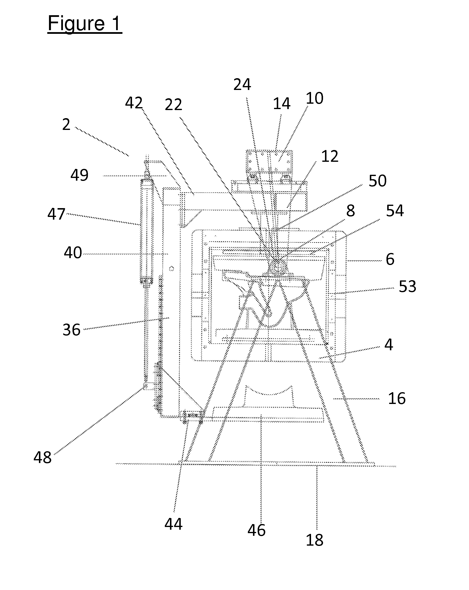
[0047]At FIG. 1, there is shown a machine, indicated generally at 2. The machine 2 comprises a support 4, a casting cell 6 and means by which the casting cell 6 can swing, pivot, tilt or rotate about the support 4, which in this case is a pivot 8, which is advantageously simple, but could be a multipart joint, a track or path or a known means by which a first part can swing, pivot, tilt or rotate relative to a second part—all of which will subsequently be referred to using the shorthand term “rotating”.

[0048]The machine 2 has particular and immediate application to the production of toilet bowls and as such will be discussed in relation to them, but has general application to all spheres in which pressure casting is utilised, including particularly sanitaryware, tableware and the technical ceramics industries. The machine 2 is composed of known materials, such as metals, alloys and plastics.

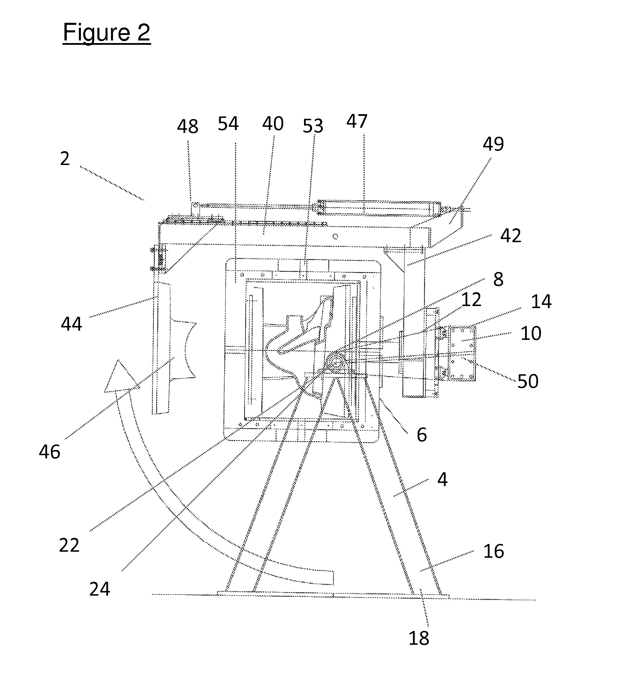
[0049]The machine 2 allows for rotation relative to one axis only, but it is possible—and wit...


PUM

PropertyMeasurementUnit
relative movementaaaaaaaaaa
length of timeaaaaaaaaaa
angleaaaaaaaaaa

Abstract

The invention comprises a pressure casting machine comprising a support and a casting cell, wherein the casting cell is attached to the support such that the casting cell can, in use, be rotated, while at least a portion of the support remains stationary, the machine further comprising a releasable retainer to retain the casting call at a user-desired rotated position.The invention also comprises a method of pressure casting comprising the steps, in this order, of filling a mould, with slip for the purpose of producing a casting when the mould is orientated at a first angle, rotating the mould so that it is orientated at a second angle; and draining the mould.The invention is best illustrated by FIG. 1 of the diagrams.

Description

FIELD OF THE INVENTION[0001]The invention relates to an apparatus and a method for pressure casting articles such as sanitaryware—including toilet bowls—in ceramic materials, In particular, the apparatus and method relate to pressure casting requiring moulds of more than two parts or cavities.BACKGROUND AND PRIOR ART[0002]Pressure casting of ceramics is a well established method of the production of tableware, sanitaryware and technical ceramics, offering an effective way of turning liquid slip into an acceptably firm, moulded body, far more quickly than is possible using traditional casting methods.[0003]This process operates thus: a preformed, microporous mould is closed using mechanical means and filled with slip or slurry. The slip / slurry is then subjected to pressure, which serves to push the water out of the slip / slurry and through the pores of the mould, leaving cast pieces of sufficient strength to support their own weight. These cast pieces are then removed from the mould, ...

Claims


Application Information

Patent Timeline
Patent Type & Authority Applications(United States)
IPC IPC(8): B28B1/28B28B1/26
CPCB28B1/28B28B1/265B28B1/261
Inventor MOORE, CHRISTOPHER
Owner PCL CERAMICS
Why Eureka
Try Eureka