Blanking of electron beam during dynamic focal spot jumping in circumferential direction of a rotating anode disk of an x-ray tube

a technology of rotating anode disk and electron beam, which is applied in the direction of x-ray tubes, material analysis using wave/particle radiation, instruments, etc., can solve the problem that imagers require frequent maintenance, and achieve the effect of more efficient us

Active Publication Date: 2015-04-09
KONINKLJIJKE PHILIPS NV
View PDF1 Cites 12 Cited by
  • Summary
  • Abstract
  • Description
  • Claims
  • Application Information

AI Technical Summary

Benefits of technology

[0010]The proposed apparatus helps secure the advantages of the focal point shift feature without compromising power specification and tube lifetime because the electron beam is mitigated as soon as the apparatus's registration unit registers focal point shift in rotation direction and said mitigation is maintained throughout the focal point shift in that direction.
[0024]The term “partial blanking” is a relaxation of “blanking” in that it includes control actions on or in the X-ray tube that result in reducing the number of electrons per unit time to reach the anode and does include in particular reducing X-ray power.

Problems solved by technology

However it has been observed that such imagers require frequent maintenance when run at relatively high tube power.

Method used


Image

  • Blanking of electron beam during dynamic focal spot jumping in circumferential direction of a rotating anode disk of an x-ray tube
  • Blanking of electron beam during dynamic focal spot jumping in circumferential direction of a rotating anode disk of an x-ray tube
  • Blanking of electron beam during dynamic focal spot jumping in circumferential direction of a rotating anode disk of an x-ray tube

Examples


Embodiment Construction

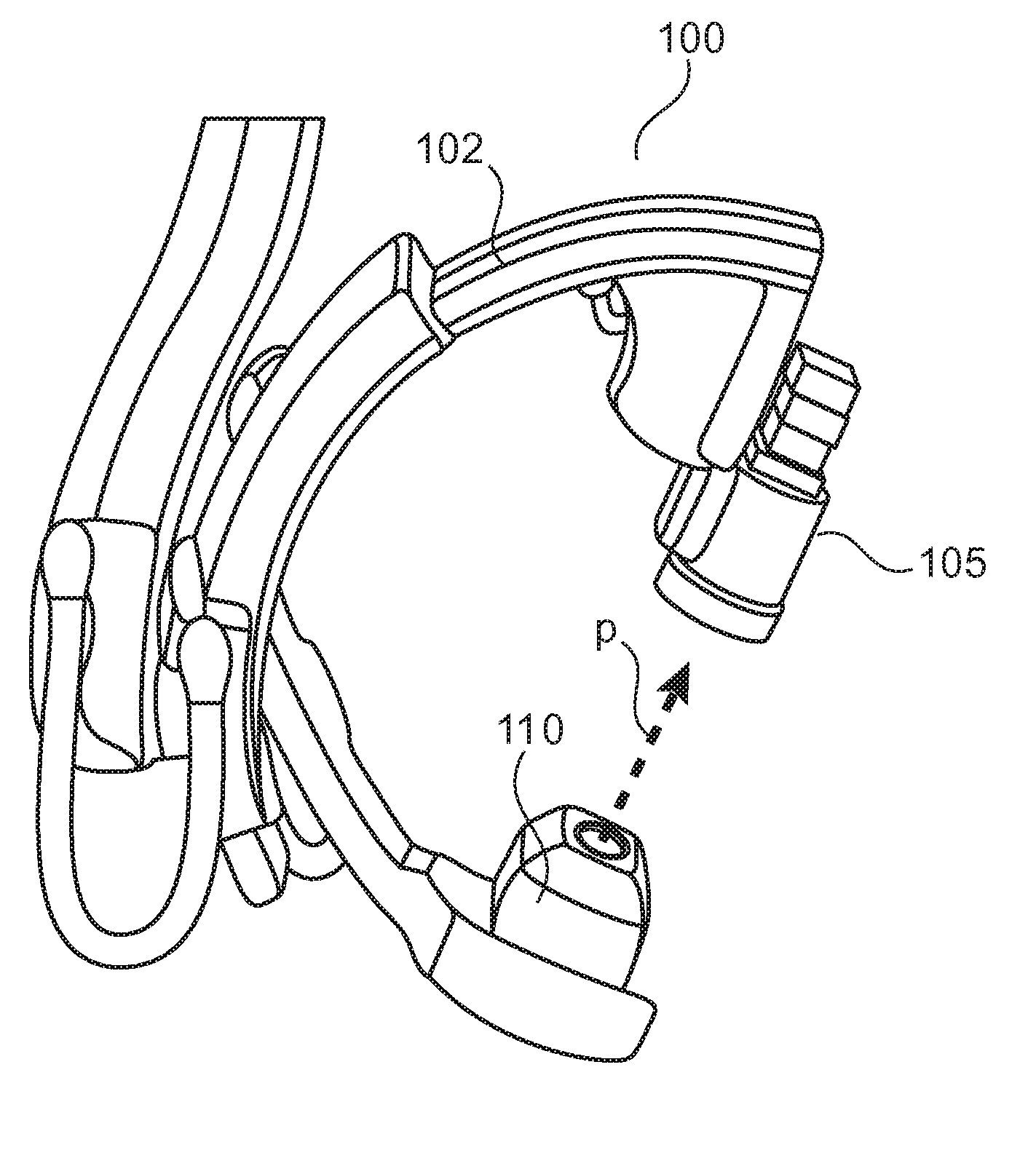
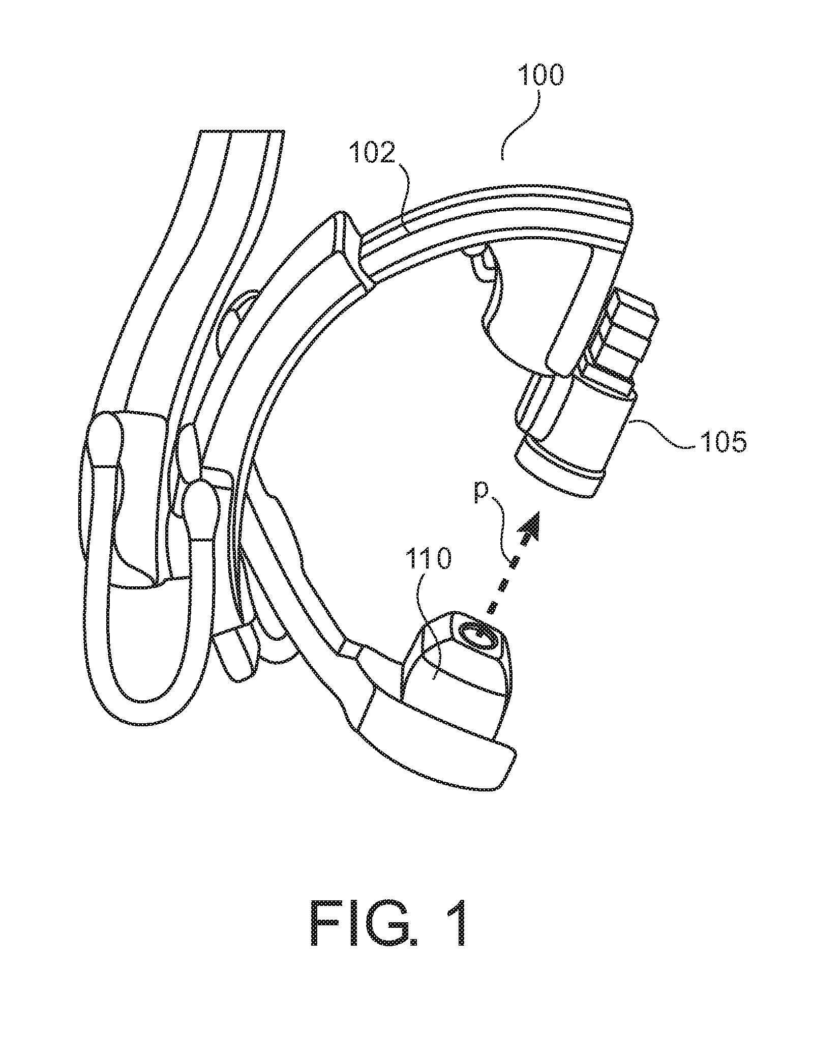
[0034]With reference to FIG. 1 there is shown an x-ray imager having a rigid gantry 102 to which are attached in opposing relationship an x-ray sensor 105 and an x-ray tube 110. FIG. 1 shows x-ray tube 110 and detector 105 in their respective outer housings or shells. X-ray 110 projects a beam of x-rays p towards detector 105. In FIG. 1 the imager is of a “C-arm” type but it is understood that the following is equally applicable to other x-ray imagers having different constructions.

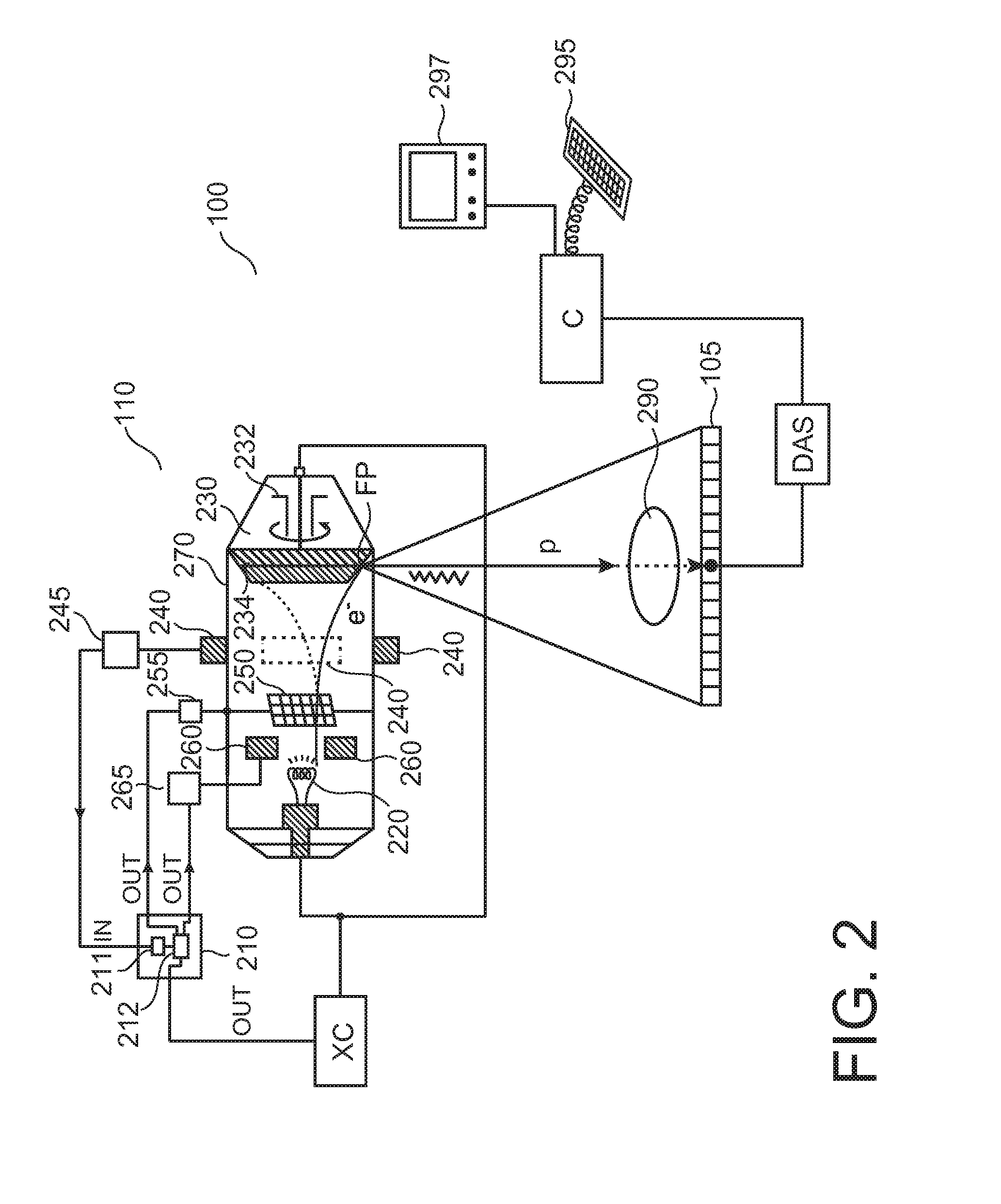
[0035]FIG. 2 shows in more detail certain components of the x-ray imager 100 in FIG. 1 in particular x-ray tube 110. X-ray tube 110 is arranged to emit x-ray p which are attenuated by tissue of an object 290 for example a patient undergoing examination whilst residing on an examination table interposed between X-ray tube 110 and detector 105. The attenuated x-ray (shown in FIG. 2 in dashed lines) interacts with detector cells of detector 105. The interaction is translated into digital signals by a data ac...


PUM

PropertyMeasurementUnit
melting temperatureaaaaaaaaaa
residence timeaaaaaaaaaa

Abstract

An apparatus (210) and method for total or partial blanking of an electron beam (e) during a jump between the 2 or more positions of a dynamic focal spot (FP) movement in circumferential direction of the electron beam impinging on the focal track (FPTR) of a rotating target disk (230) of a X-ray tube (110). Alternatively the focal spot size can be increased during this short time interval. Overheating of the anode at the focal spot can be prevented.

Description

FIELD OF THE INVENTION[0001]The present invention relates to an apparatus for controlling an X-ray tube with shiftable focal point capability having a movable anode, to a method of controlling an X-ray tube with shiftable focal point capability having a movable anode, to an x-ray tube, to a medical x-ray imager, to a computer program element, and to a computer readable medium.BACKGROUND OF THE INVENTION[0002]Some medical X-ray imagers have X-ray tubes with rotating anode disks and a further dynamic feature that allows changing by means of electric or magnetic fields the direction of the electron beam incident on the rotating anode. This dynamic focal spot movement helps increase image quality, that is less noise and higher resolution are achievable without increasing power or decreasing focal spot size. However it has been observed that such imagers require frequent maintenance when run at relatively high tube power. An imager with a rotatable anode is described in US 2011 / 0280376.S...

Claims


Application Information

Patent Timeline
Patent Type & Authority Applications(United States)
IPC IPC(8): H01J35/14H01J35/30G01N23/225H01J35/24
CPCH01J35/14G01N23/2252H01J35/30H01J35/24A61B6/4021A61B6/405A61B6/4441A61B6/54H01J35/147H01J35/153H01J35/305H05G1/34H05G1/46
Inventor BATHE, CHRISTOPH HELMUTREPENNING, THORBEN
Owner KONINKLJIJKE PHILIPS NV
Why Eureka
Try Eureka