High incidence angle retroreflective sheeting

a retroreflective sheeting and high incidence angle technology, applied in the field of retroreflective materials, can solve the problems of limiting use, losing nearly all of the reflectivity, and the apparent brightness of conventional retroreflective materials with the increase of the incidence angle, so as to achieve the effect of maximizing the retroreflectivity

Inactive Publication Date: 2016-01-14
VASYLYEV SERGIY
View PDF13 Cites 14 Cited by
  • Summary
  • Abstract
  • Description
  • Claims
  • Application Information

AI Technical Summary

Benefits of technology

[0014]The present invention solves problems of retroreflecting light at high incidence within a thin sheet-form structure having a top optically transmissive layer and a bottom reflective layer. The top layer includes at least one parallel array of straight and narrow channels formed within the layer's material. The channels may also be arranged in two parallel array oriented perpendicular to each other. The channels have smooth parallel surfaces which are configured to reflect light propagating through the top layer by means of a total internal reflection (TIR). The channels may be spaced according to a predefined ratio with respect to the channel depth to maximize retroreflectivity for a particular angular range. The bottom reflective layer may include a mirrored surface and may also be configured to include linear prismatic surface corrugations extending perpendicular to the channels of the top layer. Each of the corrugations should preferably be shaped in the form of an isosceles right-angle linear prism which retroreflects light at least in one plane which is perpendicular to the longitudinal axis of the prism and parallel to the linear channels of the top layer. The retroreflective sheeting may be preferably operable in an orientation in which the incident light enters the surface of the sheet-form structure at an off-normal angle and in which the channels of the top layer are perpendicular or near perpendicular to the incident light direction.

Problems solved by technology

However, the retroreflective properties and, hence, the apparent brightness of conventional retroreflective materials diminishes rapidly with the increase of the incidence angle.
For example, the cube corner retroreflective sheeting, which provides some of the highest reflectivity of any known retroreflective sheeting, loses nearly all of its reflectivity when the incidence angle becomes greater than about 40°, which limits its use.
Raised retroreflective elements or retroreflectors consisting of array of individually assembled retroreflective elements have been proposed which lack the utility and cost benefits of continuous retroreflective sheeting.

Method used


Image

  • High incidence angle retroreflective sheeting
  • High incidence angle retroreflective sheeting
  • High incidence angle retroreflective sheeting

Examples


example 1

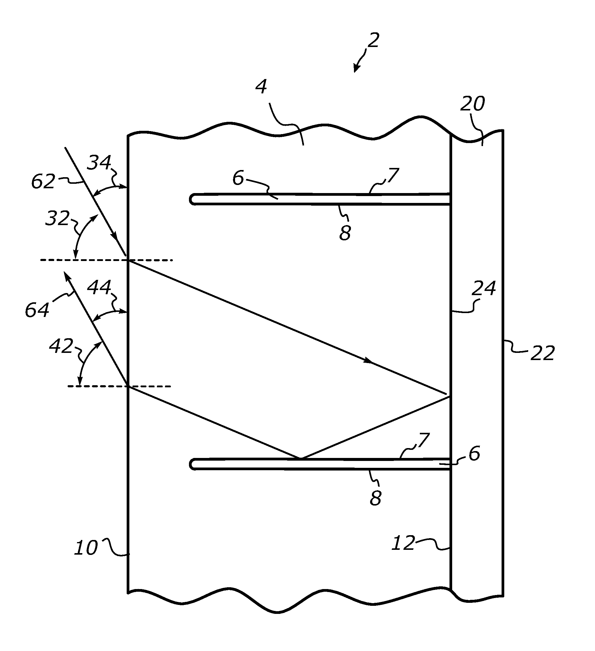
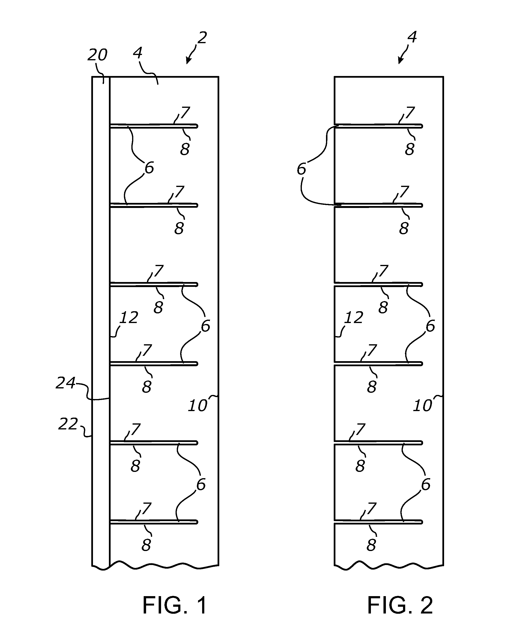
[0165]A retroreflective sheet-form structure as schematically illustrated in FIG. 7 was made by attaching a top optically transmissive layer formed by a 1-millimeter-thick sheet of optically clear thermoplastic polyurethane (TPU) to a bottom reflective layer formed by a same-sized sheet of brightness enhancement film BEF II 90 / 24 commercially available from 3M Corporation and having a thickness of about 140 μm (5.5 mils). The BEF II 90 / 24 film product has a microprismatic surface structure formed by an array of right-angle isosceles microprisms having a linear configuration and prism pitch of about 24 μm (0.9 mils).

[0166]An array of parallel TIR micro-channels was formed in the top layer by slitting a surface of the TPU sheet material to a cutting depth of approximately 500 μm using a pack of sharp rotary blades commercially available from KAI Corporation. The micro-channels were formed at a constant spacing of about 600 μm so that the L / D ratio characterizing the channels was about...

example 2

[0170]A retroreflective sheet-form structure as was made as described in EXAMPLE 1 above except that the top layer was made from optically clear plasticized polyvinyl chloride (flexible polyvinyl film). The tests were conducted as described in EXAMPLE 1 above and have shown similar results.

example 3

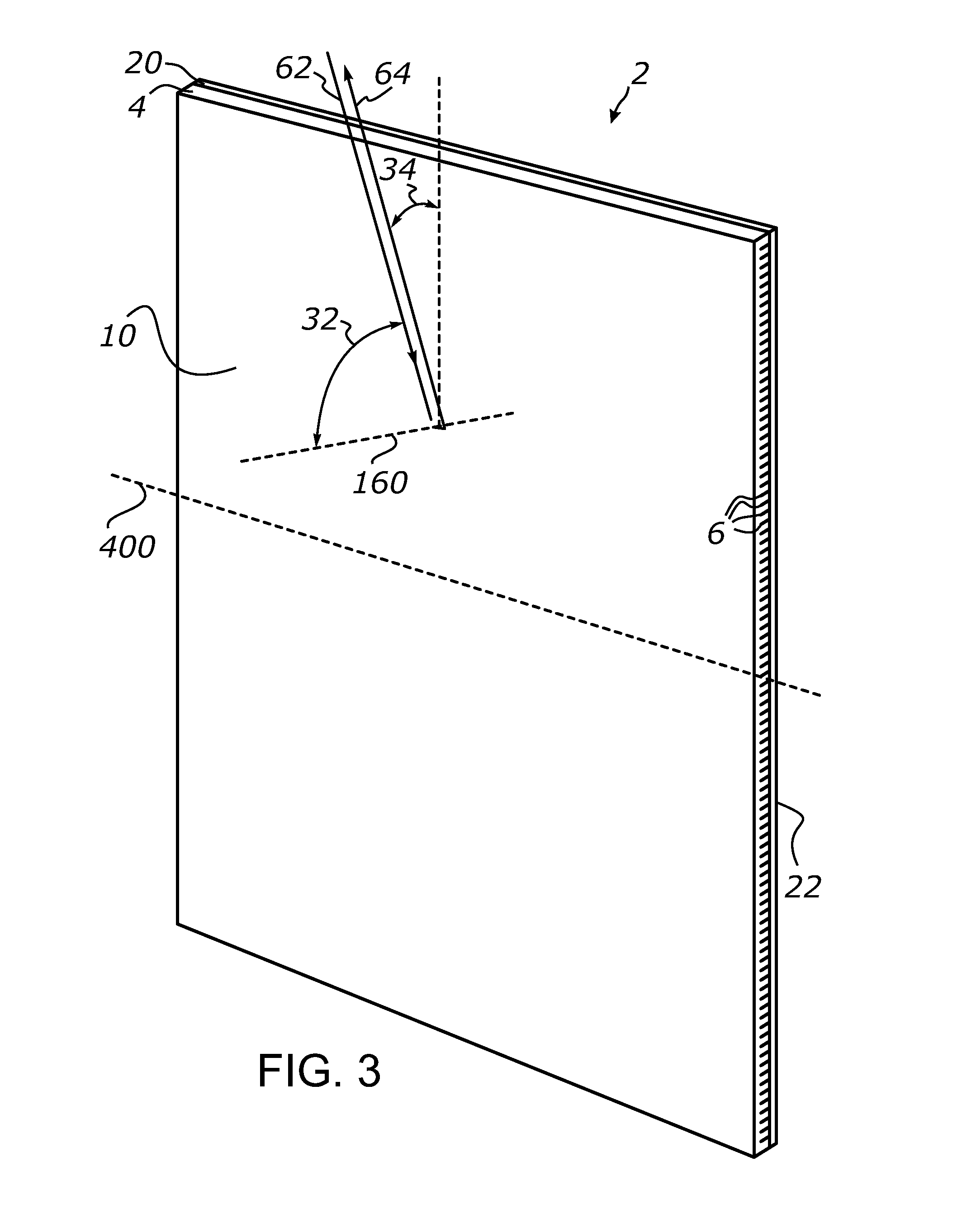
[0171]A retroreflective sheet-form structure as schematically illustrated in FIG. 3 was made by a top optically transmissive layer formed by a 0.5-millimeter-thick sheet of optically clear thermoplastic polyurethane (TPU) and attaching it to a bottom reflective layer formed by a metalized polyethylene terephthalate (Mylar®) film. The top layer included an array of parallel TIR micro-channels formed as described in EXAMPLE 1 above and spaced / dimensioned at 1.4 L / D ratio.

[0172]The bottom layer was provided with a high-tack adhesive that was used to attach the retroreflective sheet-form structure to a thin and rigid sheet-form substrate. A strip of approximately 4 centimeters by 50 centimeters of the resulting sheet-form retroreflective structure was cut out such that the longitudinal axis of the strip was parallel to the longitudinal axis of the micro-channels formed in the top layer. The resulting strip was tested by exposing it to a parallel beam of light and measuring its reflectan...


PUM

PropertyMeasurementUnit
angleaaaaaaaaaa
roughness parameteraaaaaaaaaa

Abstract

A retroreflective sheeting is disclosed which comprises a top transmissive layer including a plurality of parallel channel formed perpendicular to a surface of the layer, and a reflective bottom layer including a specular surface or a corrugated transmitting surface. The corrugated surface includes a plurality of linear prismatic elements extending perpendicular to the channels of the top layer. The top and bottom layers reflect light in orthogonal directions and act cooperatively to retroreflect incident light back toward the source, particularly at high incidence angles. Various light management devices employing the retroreflective sheeting are also disclosed.

Description

CROSS-REFERENCE TO RELATED APPLICATIONS[0001]This application claims priority from U.S. provisional application Ser. No. 62 / 024,444 filed on Jul. 14, 2014, incorporated herein by reference in its entirety.STATEMENT REGARDING FEDERALLY SPONSORED RESEARCH OR DEVELOPMENT[0002]Not ApplicableINCORPORATION-BY-REFERENCE OF MATERIAL SUBMITTED ON A COMPACT DISC[0003]Not ApplicableNOTICE OF MATERIAL SUBJECT TO COPYRIGHT PROTECTION[0004]A portion of the material in this patent document is subject to copyright protection under the copyright laws of the United States and of other countries. The owner of the copyright rights has no objection to the facsimile reproduction by anyone of the patent document or the patent disclosure, as it appears in the United States Patent and Trademark Office publicly available file or records, but otherwise reserves all copyright rights whatsoever. The copyright owner does not hereby waive any of its rights to have this patent document maintained in secrecy, inclu...

Claims


Application Information

Patent Timeline
Patent Type & Authority Applications(United States)
IPC IPC(8): G02B5/136G02B1/04G02B5/02
CPCG02B5/136G02B5/0284G02B1/04C08L27/06C08L75/04C08L2207/04G02B5/0231
Inventor VASYLYEV, SERGIY
Owner VASYLYEV SERGIY
Why Eureka
Try Eureka