

Imaging lens
a technology of chromatic aberration and lens, applied in the field of imaging lenses, can solve the problems of insufficient brightness, insufficient to meet the demand for a wide field of view, and difficult to correct aberrations in the peripheral area of images, so as to suppress ghost phenomena, correct chromatic aberrations, and low profile. the effect of profil
- Summary
- Abstract
- Description
- Claims
- Application Information
AI Technical Summary
Benefits of technology
Problems solved by technology
Method used
Image

Examples
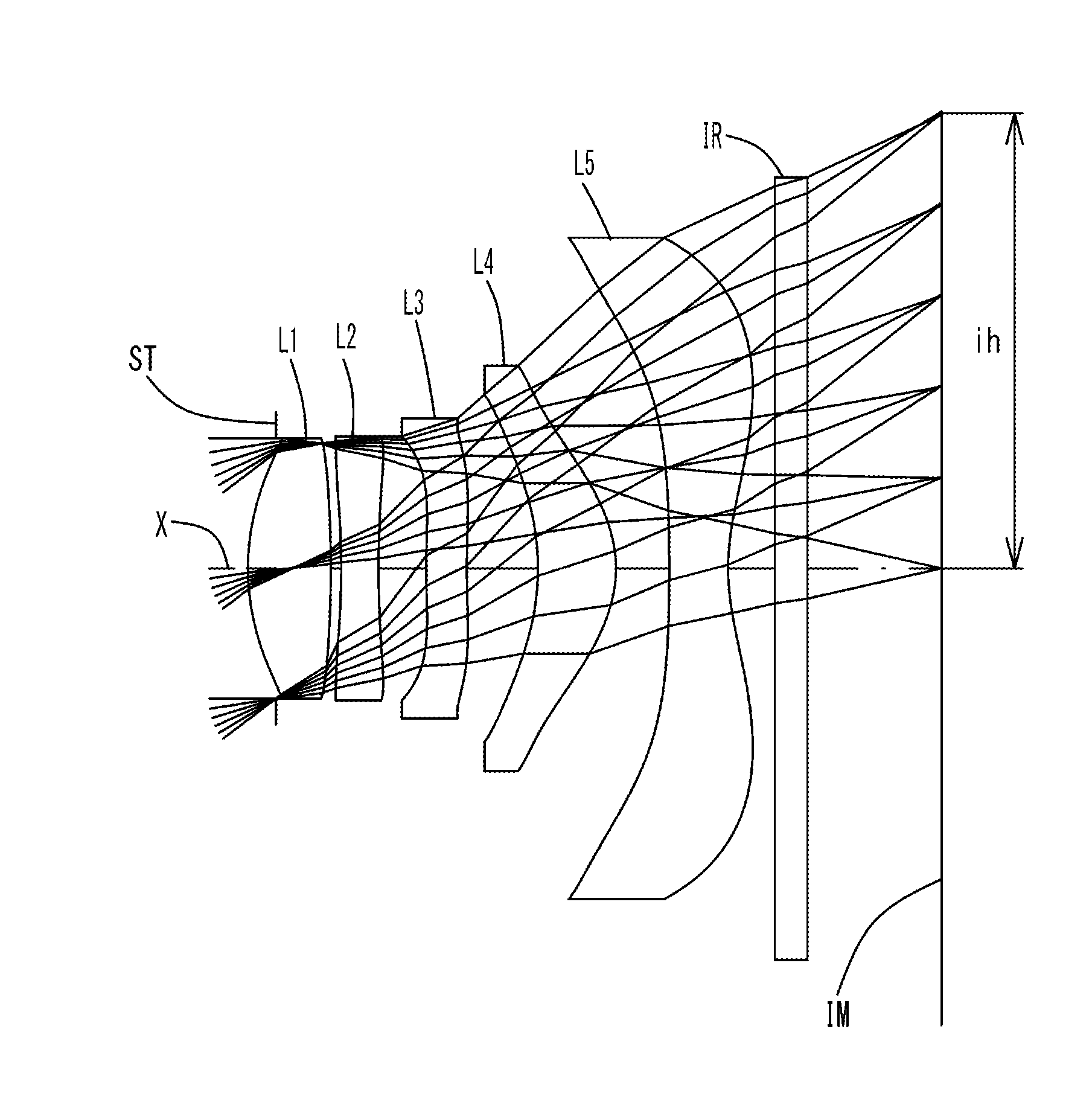
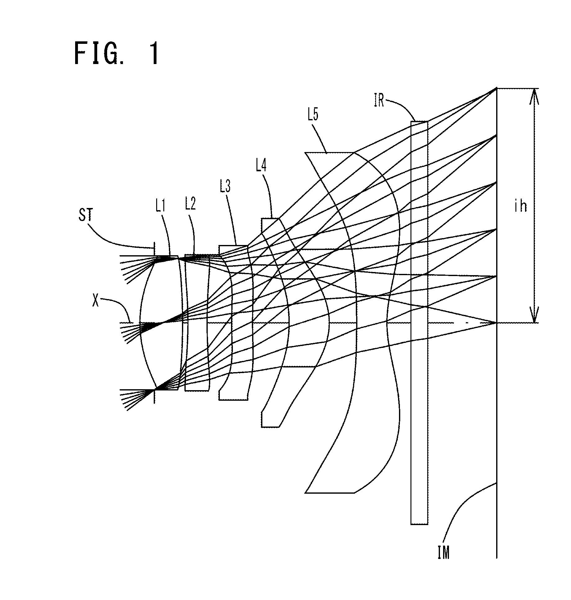
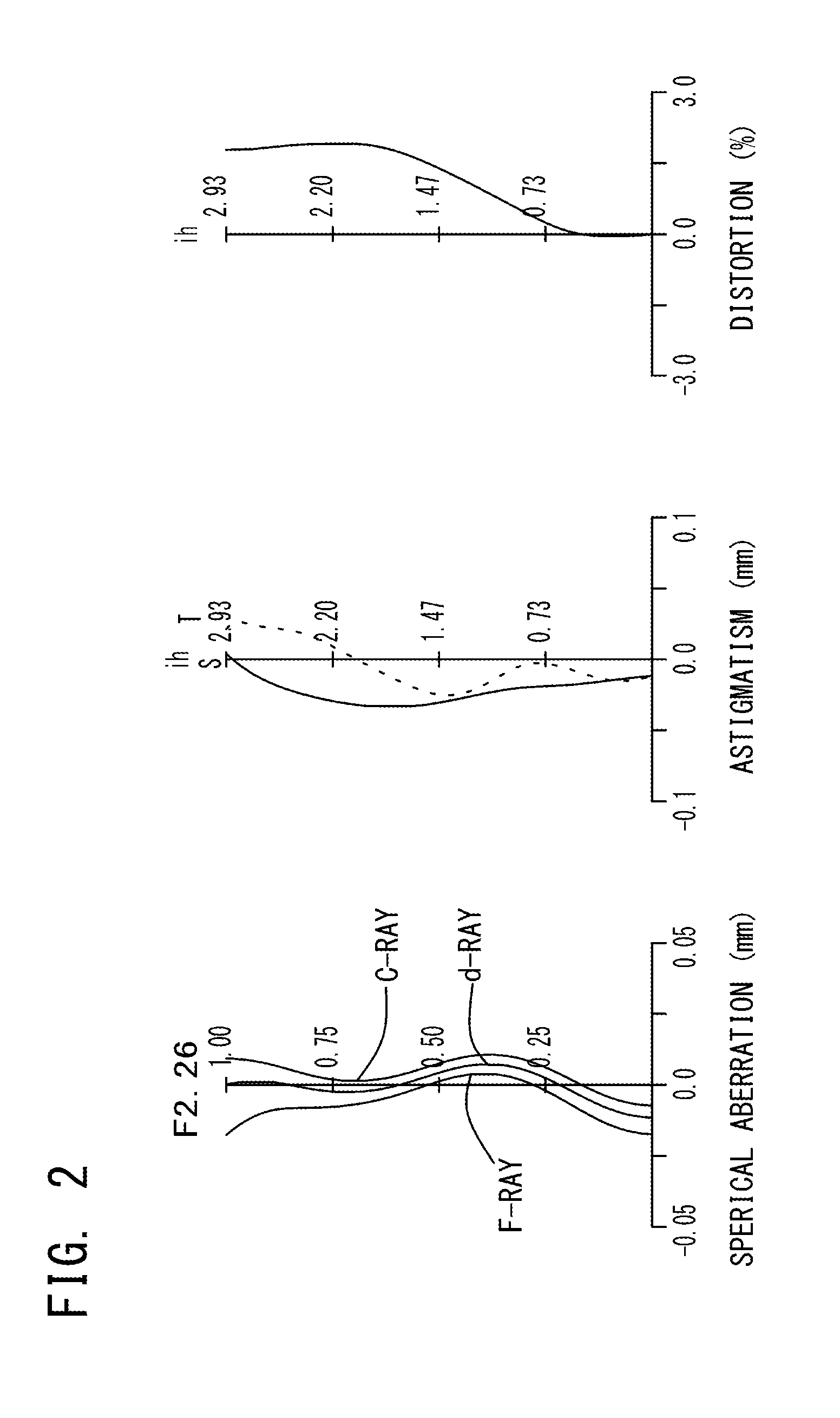
example 1
[0116]The basic lens data of Example 1 is shown in Table 1 below.
TABLE 1Example 1 in mmf = 3.782Fno = 2.26ω(°) = 37.2TTL = 4.4ih = 2.93Surface DataCurvatureSurfaceRefractiveAbbeSurface No. iRadius rDistance dIndex NdNumber νd(Object Surface)InfinityInfinity1 (Stop)Infinity−0.1802*1.5250.5321.54455.573*−8.5710.0674*−4.9320.2391.63923.255*5.8990.3076*6.1570.2611.63923.257*6.7310.4568*−1.6210.5021.53555.669*−0.8050.34310* −11.8060.3771.53555.6611* 1.3780.30012 Infinity0.2101.51764.1713 Infinity0.847Image PlaneInfinityConstituent Lens DataLensStart SurfaceFocal Length122.42624−4.1673696.086482.465510−2.284Aspheric Surface Data2nd Surface3rd Surface4th Surface5th Surface6th Surfacek1.968E−010.000E+000.000E+00−8.601E+000.000E+00A4−3.519E−02 −9.821E−02 −7.731E−02 −1.138E−01−3.901E−01 A66.053E−025.790E−019.148E−01 4.972E−011.254E−01A8−2.964E−01 −1.880E+00 −2.703E+00 −1.389E+00−7.860E−01 A104.222E−013.545E+004.982E+00 2.368E+001.428E+00A12−3.530E−01 −3.839E+00 −5.225E+00 −2.548E+00−1.258E+00...
example 2
[0120]The basic lens data of Example 2 is shown in Table 2 below.
TABLE 2Example 2 in mmf = 3.774Fno = 2.27ω(°) = 37.3TTL = 4.4ih = 2.93Surface DataCurvatureSurfaceRefractiveAbbeSurface No. iRadius rDistance dIndex NdNumber νd(Object Surface)InfinityInfinity1 (Stop)Infinity−0.1802*1.5170.5321.54455.573*−9.3240.0664*−5.4690.2431.63923.255*5.4710.3036*8.4630.2601.63923.257*8.6840.4588*−1.5980.4841.53555.669*−0.7950.34510* −15.7180.3761.53555.6611* 1.3430.30012 Infinity0.2101.51764.1713 Infinity0.860Image PlaneInfinityConstituent Lens DataLensStart SurfaceFocal Length122.44124−4.24336356.035482.443510−2.295Aspheric Surface Data2nd Surface3rd Surface4th Surface5th Surface6th Surfacek1.978E−010.000E+000.000E+00−1.638E+000.000E+00A4−3.534E−02 −1.021E−01 −7.955E−02 −1.088E−01−3.914E−01 A66.089E−025.811E−019.173E−01 4.886E−011.264E−01A8−2.966E−01 −1.874E+00 −2.702E+00 −1.394E+00−8.192E−01 A104.244E−013.535E+004.988E+00 2.401E+001.424E+00A12−3.550E−01 −3.847E+00 −5.214E+00 −2.561E+00−1.170E+0...
example 3
[0124]The basic lens data of Example 3 is shown in Table 3 below.
TABLE 3Example 3 in mmf = 3.785Fno = 2.27ω(°) = 37.2TTL = 4.4ih = 2.93Surface DataCurvatureSurfaceRefractiveAbbeSurface No. iRadius rDistance dIndex NdNumber νd(Object Surface)InfinityInfinity1 (Stop)Infinity−0.1802*1.5460.5001.54455.573*−8.8150.0694*−5.0360.2381.63923.255*5.4980.3226*3.8200.2501.63923.257*4.2720.4598*−1.6500.4941.53555.669*−0.8330.37710* −11.5720.3881.53555.6611* 1.4630.30012 Infinity0.2101.51764.1713 Infinity0.832Image PlaneInfinityConstituent Lens DataLensStart SurfaceFocal Length122.46024−4.0773646.538482.598510−2.403Aspheric Surface Data2nd Surface3rd Surface4th Surface5th Surface6th Surfacek1.097E−010.000E+000.000E+006.865E+000.000E+00A4−3.978E−02 −1.140E−01 −6.813E−02 −1.058E−01 −3.783E−01 A65.500E−025.690E−019.081E−015.300E−011.508E−01A8−3.079E−01 −1.882E+00 −2.700E+00 −1.431E+00 −8.083E−01 A104.082E−013.563E+005.028E+002.432E+001.409E+00A12−3.530E−01 −3.839E+00 −5.225E+00 −2.548E+00 −1.258E+00...
PUM
 Abstract
Description
Claims
Application Information