Method for Calibrating Cameras with Non-Overlapping Views

a non-overlapping view and camera technology, applied in the field of cameras, can solve the problems of limited accuracy, inapplicability to stationary cameras, and methods that cannot determine all the 6 degrees of freedom (dof) of poses, and achieve the effect of fewer degeneracy problems

Active Publication Date: 2016-01-14
MITSUBISHI ELECTRIC CORP
View PDF12 Cites 152 Cited by
  • Summary
  • Abstract
  • Description
  • Claims
  • Application Information

AI Technical Summary

Benefits of technology

[0007]The method has fewer degeneracy problems compared to hand-eye calibration techniques. The method can calibrate a number of cameras, or a moving camera at a large nu...

Problems solved by technology

However, that method cannot determine all the 6 degrees-of-freedom (DOF) of the poses when specific. motions or camera configurations are used.
The above methods use the motion of the moving plat...

Method used


Image

  • Method for Calibrating Cameras with Non-Overlapping Views
  • Method for Calibrating Cameras with Non-Overlapping Views
  • Method for Calibrating Cameras with Non-Overlapping Views

Examples


Embodiment Construction

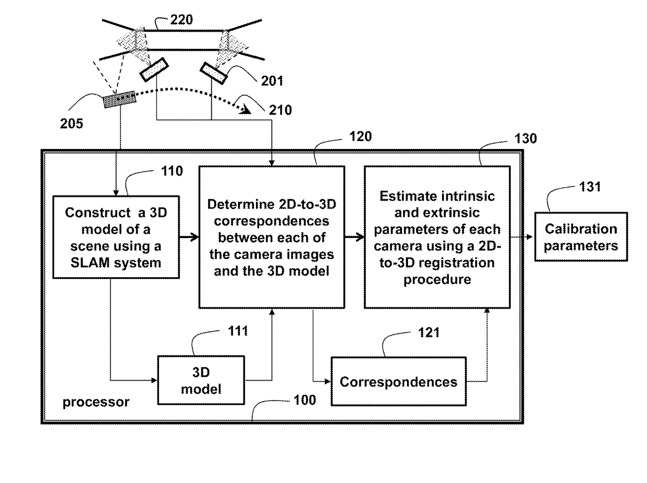
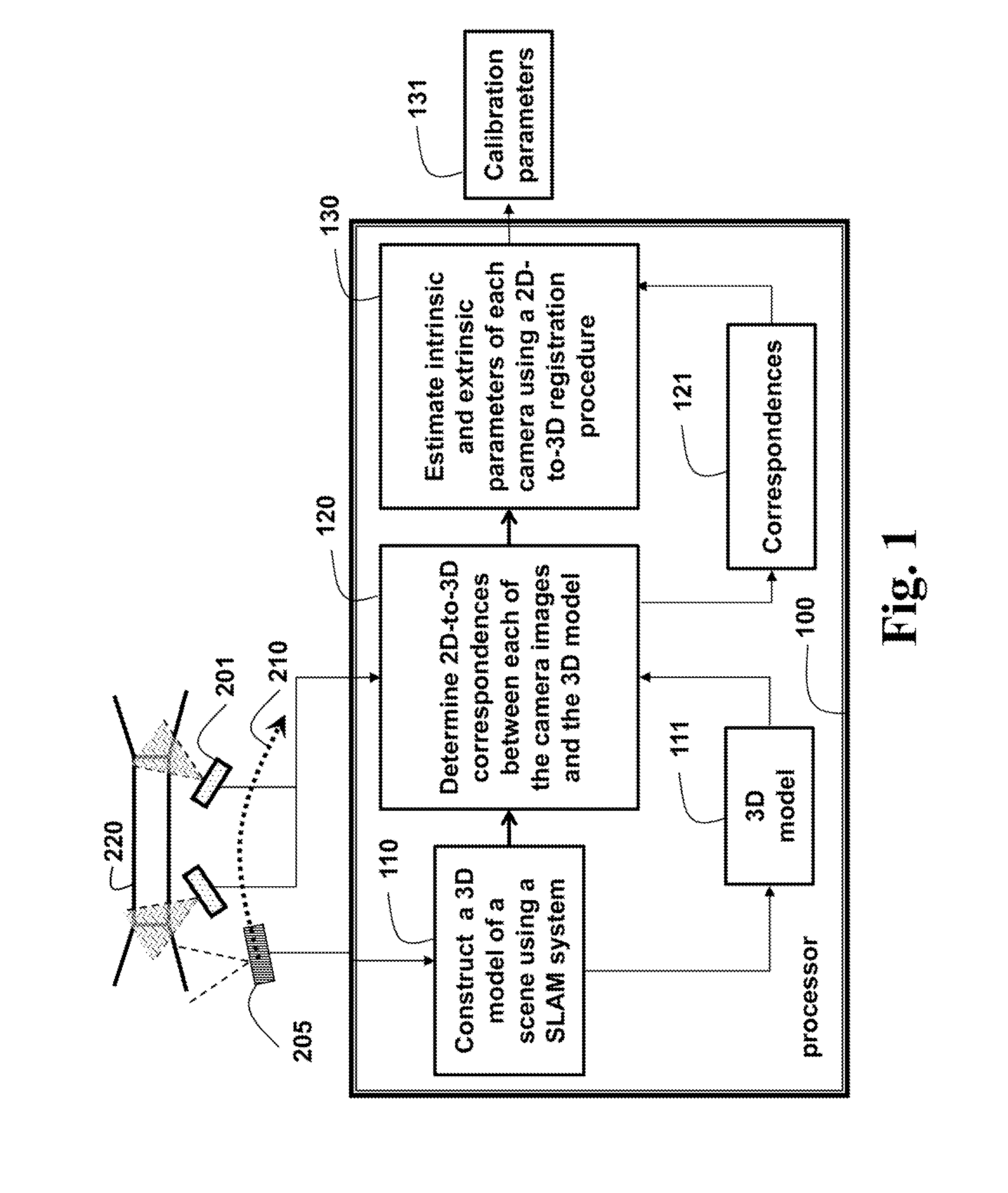
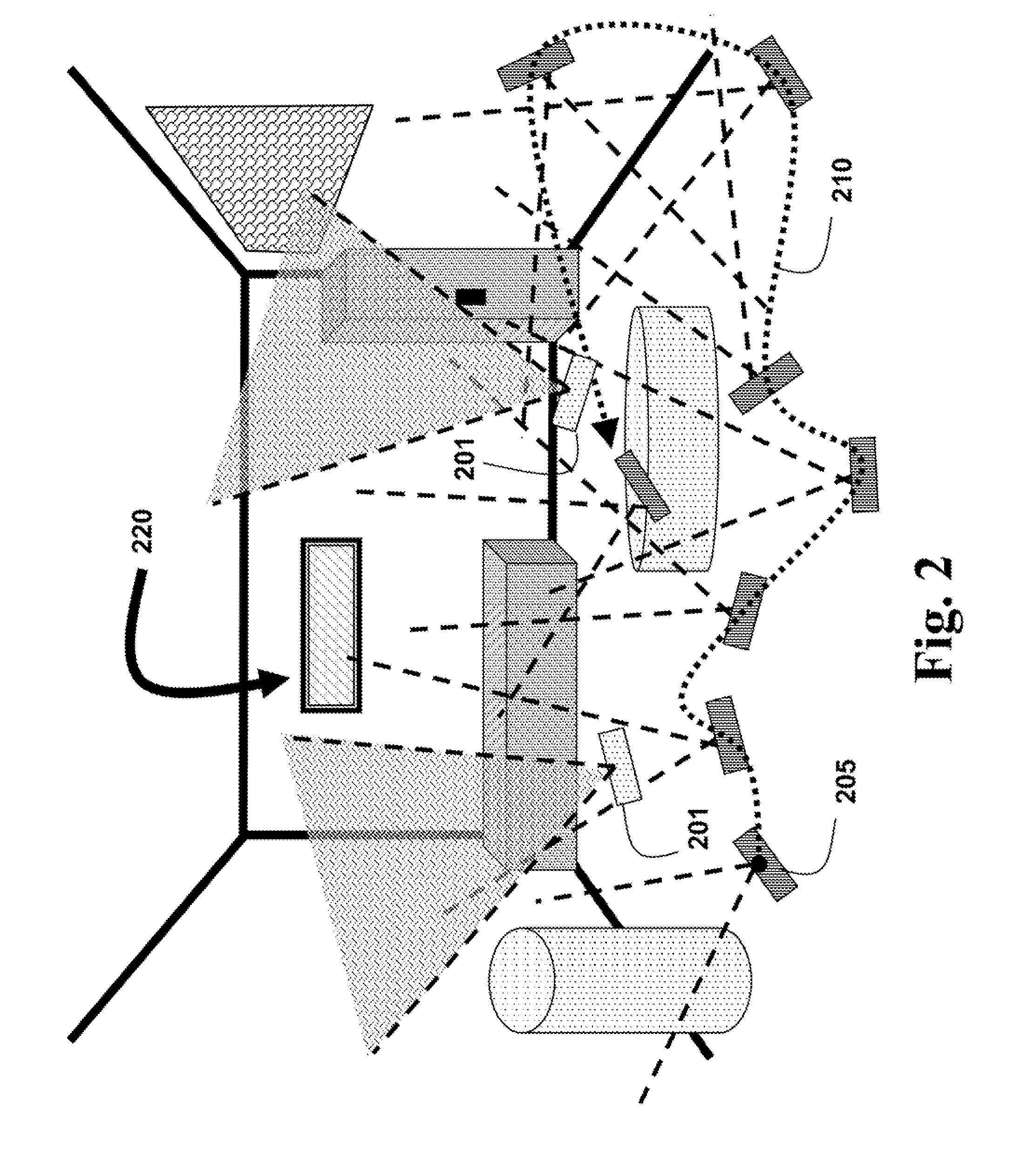
[0012]FIGS. 1 and 2 show a method for calibrating one or more cameras 201 with non-overlapping views of a scene 220 according to embodiments of our invention. The method determines intrinsic and extrinsic camera calibration parameters. The intrinsic parameters include, e.g., focal length, and radial distortion parameters of the camera. The extrinsic parameters include the poses, including 3D translation and 3D rotation, of the cameras.

[0013]A three-dimensional (3D) model 111 of the scene is constructed 110 using a simultaneous localization and mapping (SLAM) procedure. A calibration camera 205 used by the SLAM procedure is independent of the one or more cameras 201 to be calibrated. Correspondences 121 between images acquired by the one or more cameras 201 and the 3D model are determined 120. Then, intrinsic and extrinsic calibration parameters 131 are determined using a 2D-to-3D registration procedure 130.

[0014]The method can be performed in a processor 100 connected to memory and ...


PUM


Abstract

A method calibrates one or more cameras, wherein the one or more cameras acquire images of a scene for different viewpoints, and wherein the images are non-overlapping, by first constructing a 3D model of the scene using a calibration camera that is independent of the one or more cameras, and a. simultaneous localization and mapping (SLAM) procedure. 2D-to-3D correspondences between each of the images and the 3D model are determined. Then, calibration parameters of each of the one or more cameras are estimated using a 2D-to-3D registration procedure.

Description

FIELD OF THE INVENTION[0001]The invention is generally related to calibrating cameras, and more particularly to calibrating cameras with non-overlapping views.BACKGROUND OF THE INVENTION[0002]Calibrating cameras where all views overlap each other is relatively simple. This is not the case when the views of the cameras are non-overlapping.[0003]There are several known methods for calibrating multiple cameras with non-overlapping views. In one method, the multiple cameras are rigidly attached to a moving platform (e.g., a vehicle and a mobile robot) so that the cameras do not move with respect to each other. That method first determines a motion of each camera by using a simultaneous localization and mapping (SLAM) procedure for a sequence of images obtained with the camera. Then, that method matches the motions of the multiple cameras using a hand-eye calibration method, Which provides the relative poses between the cameras. However, that method cannot determine all the 6 degrees-of-...

Claims


Application Information

Patent Timeline
IPC IPC(8): G06T7/00H04N13/02H04N17/00
CPCG06T7/0018G06T7/0028G06T2207/10028H04N13/0257H04N13/0203H04N17/002G06T7/80G06T7/33H04N13/204H04N13/257
Inventor TAGUCHI, YUICHICANSIZOGLU, ESRARAMALINGAM, SRIKUMARMIKI, YOHEI
Owner MITSUBISHI ELECTRIC CORP
Why Eureka
Try Eureka