Storage battery, control method of storage battery, control device, and control method
a storage battery and control method technology, applied in the direction of transportation and packaging, secondary cell servicing/maintenance, electrochemical generators, etc., can solve the problems of storage battery exchange with a new storage battery, charge timing becomes faster, etc., and achieve the effect of suppressing battery capacity deterioration
- Summary
- Abstract
- Description
- Claims
- Application Information
AI Technical Summary
Benefits of technology
Problems solved by technology
Method used
Image

Examples
first embodiment
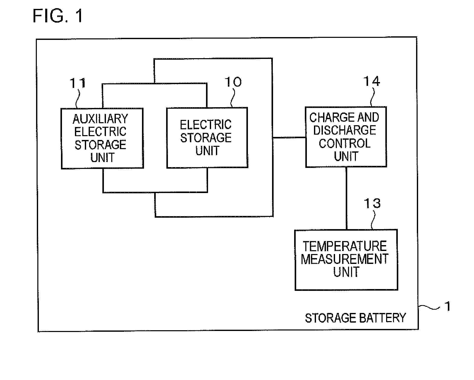
[0030]In FIG. 1, an example of a functional block diagram of a storage battery 1 of this embodiment is illustrated. As illustrated, the storage battery 1 includes an electric storage unit (a first electric storage unit) 10, an auxiliary electric storage unit (a second electric storage unit) 11, a temperature measurement unit 13, and a charge and discharge control unit 14. Hereinafter, each unit will be described.
[0031]The electric storage unit 10 is configured of one or a plurality of battery cells. The plurality of battery cells configuring the electric storage unit 10 are connected to each other in series and / or in parallel. The electric storage unit 10, for example, is able to be configured of a lithium ion secondary battery or a lead storage battery.
[0032]The auxiliary electric storage unit 11 is configured of one or a plurality of battery cells, and is connected to the electric storage unit 10 in parallel. The plurality of battery cells configuring the auxiliary electric storag...
second embodiment
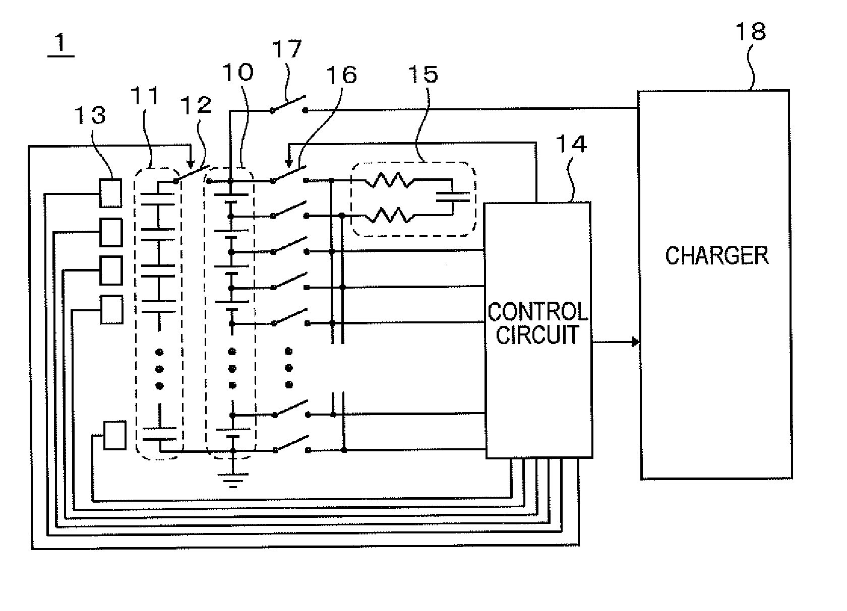
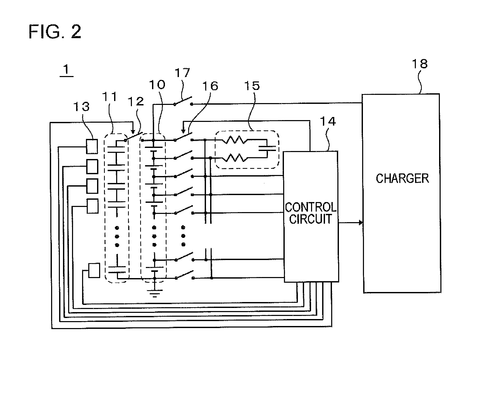
[0052]This embodiment is an embodiment in which the storage battery 1 of the first embodiment is more specified. In FIG. 2, an example of the configuration of the storage battery 1 of this embodiment is illustrated.
[0053]As illustrated, the storage battery 1 includes the electric storage unit 10, the auxiliary electric storage unit 11, a switch 12, the temperature measurement unit 13, the charge and discharge control unit (a control circuit) 14, a balance circuit 15, a switch 16, and a switch 17. The storage battery 1 is connected to a charger 18 through an external connection terminal for charge and discharge.
[0054]The electric storage unit 10 has a configuration in which a plurality of lithium ion secondary battery cells are connected in series. The energy density of the electric storage unit 10, for example, is able to be greater than or equal to 100 Wh / kg.
[0055]The auxiliary electric storage unit 11 has a configuration in which a plurality of capacitor cells (an electric double ...
third embodiment
[0076]This embodiment is an embodiment in which the storage battery 1 of the first embodiment is more specified. In FIG. 4, an example of the configuration of the storage battery 1 of this embodiment is illustrated.
[0077]As illustrated, the storage battery 1 includes the electric storage unit 10, the auxiliary electric storage unit 11 (sub-auxiliary electric storage units 11a and 11b), switches 12a and 12b, the temperature measurement unit 13, the charge and discharge control unit (the control circuit) 14, the balance circuit 15, the switch 16, and the switch 17. The storage battery 1 is connected to the charger 18.
[0078]The electric storage unit 10, the temperature measurement unit 13, the balance circuit 15, the switch 16, and the switch 17 are identical to those of the second embodiment.
[0079]The auxiliary electric storage unit 11 includes two rows of the sub-auxiliary electric storage units 11a and 11b. Each of the sub-auxiliary electric storage units 11a and 11b is configured o...
PUM
 Abstract
Description
Claims
Application Information
 - R&D
- Intellectual Property
- Life Sciences
- Materials
- Tech Scout
- Unparalleled Data Quality
- Higher Quality Content
- 60% Fewer Hallucinations
Browse by: Latest US Patents, China's latest patents, Technical Efficacy Thesaurus, Application Domain, Technology Topic, Popular Technical Reports.
© 2025 PatSnap. All rights reserved.Legal|Privacy policy|Modern Slavery Act Transparency Statement|Sitemap|About US| Contact US: help@patsnap.com