
Solar battery-driven object detection system

a technology of object detection and solar energy, applied in the direction of instruments, mechanical vibration actuation of burglar alarms, greenhouse gas reduction, etc., can solve the problems of limited power consumption, increase in the size of solar panels to be incorporated, increase in cost, etc., and achieve the reduction of battery capacity, power consumption of power source units, and power consumption.

Active Publication Date: 2017-02-21
OPTEX CO LTD
View PDF14 Cites 0 Cited by
  • Summary
  • Abstract
  • Description
  • Claims
  • Application Information

AI Technical Summary

Benefits of technology

The present invention provides a solar battery-driven object detection system that can perform long distance detection while reducing the battery capacity and generation capacity of the solar panel. The system controls the intensity of the detection beam to be transmitted based on the demand signal from the reception unit, ensuring optimal detection in adverse environments such as temporary fog or rain. The reduced power consumption allows for a smaller solar battery unit, which can be attained by incorporating a smaller-sized solar panel. The system also provides a manual intensity operation unit for easy adjustment of the detection beam intensity based on the detection distance. Additionally, the invention provides a security sensor including the solar battery-driven object detection system, allowing for long distance detection and securing the power source outdoors.

Problems solved by technology

With the conventional solar battery-driven object detection system, however, the intensity of the detection beam has to be increased in order to extend the detection distance, and therefore a battery having a larger capacity has to be employed to cover the increase in power consumption, which leads to an increase in size of the solar panel to be incorporated.
The increase in size of the system naturally results in an increase in cost.
Meanwhile, with the solar panel of a reduced size, a sufficient battery capacity is unable to be secured and therefore the power consumption is limited, which makes it difficult to perform long distance detection since the detection distance is shortened.

Method used


Image

  • Solar battery-driven object detection system
  • Solar battery-driven object detection system
  • Solar battery-driven object detection system

Examples


Embodiment Construction

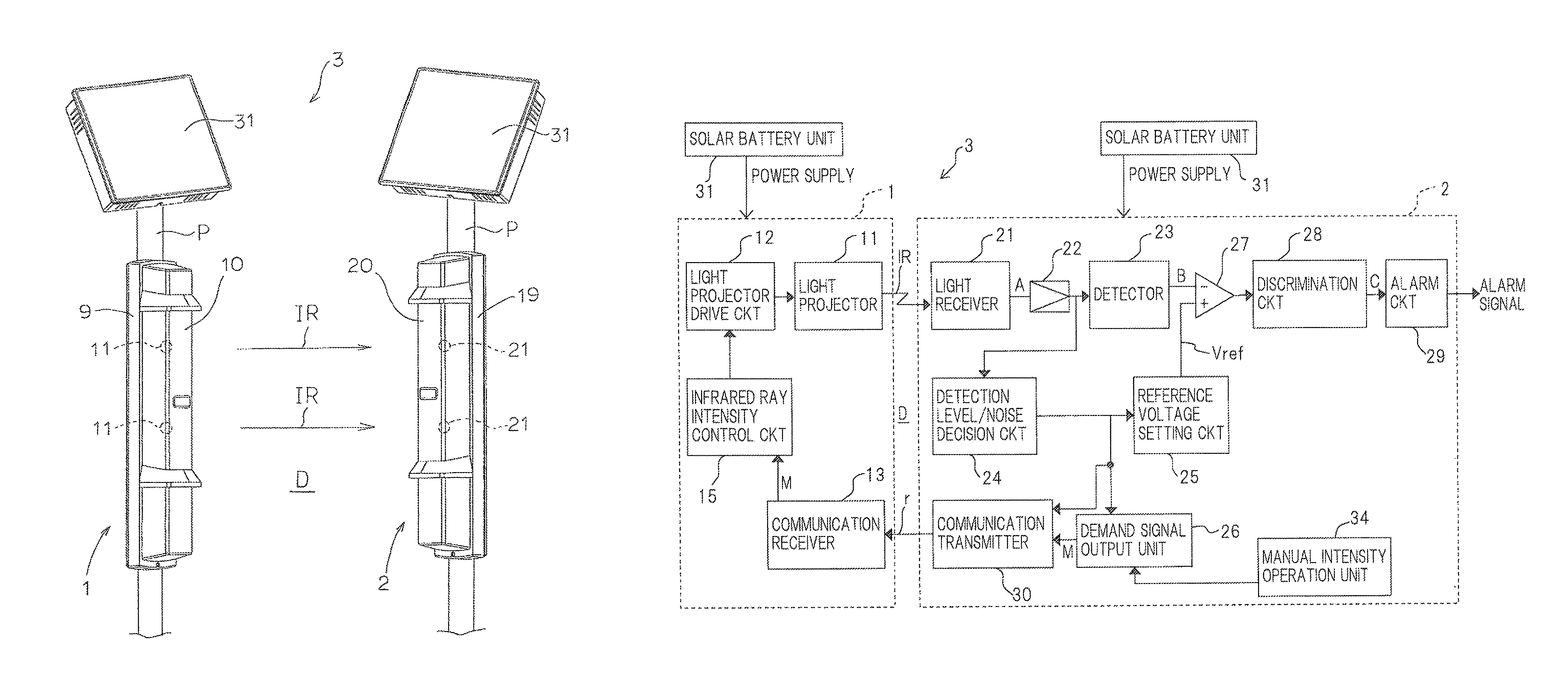
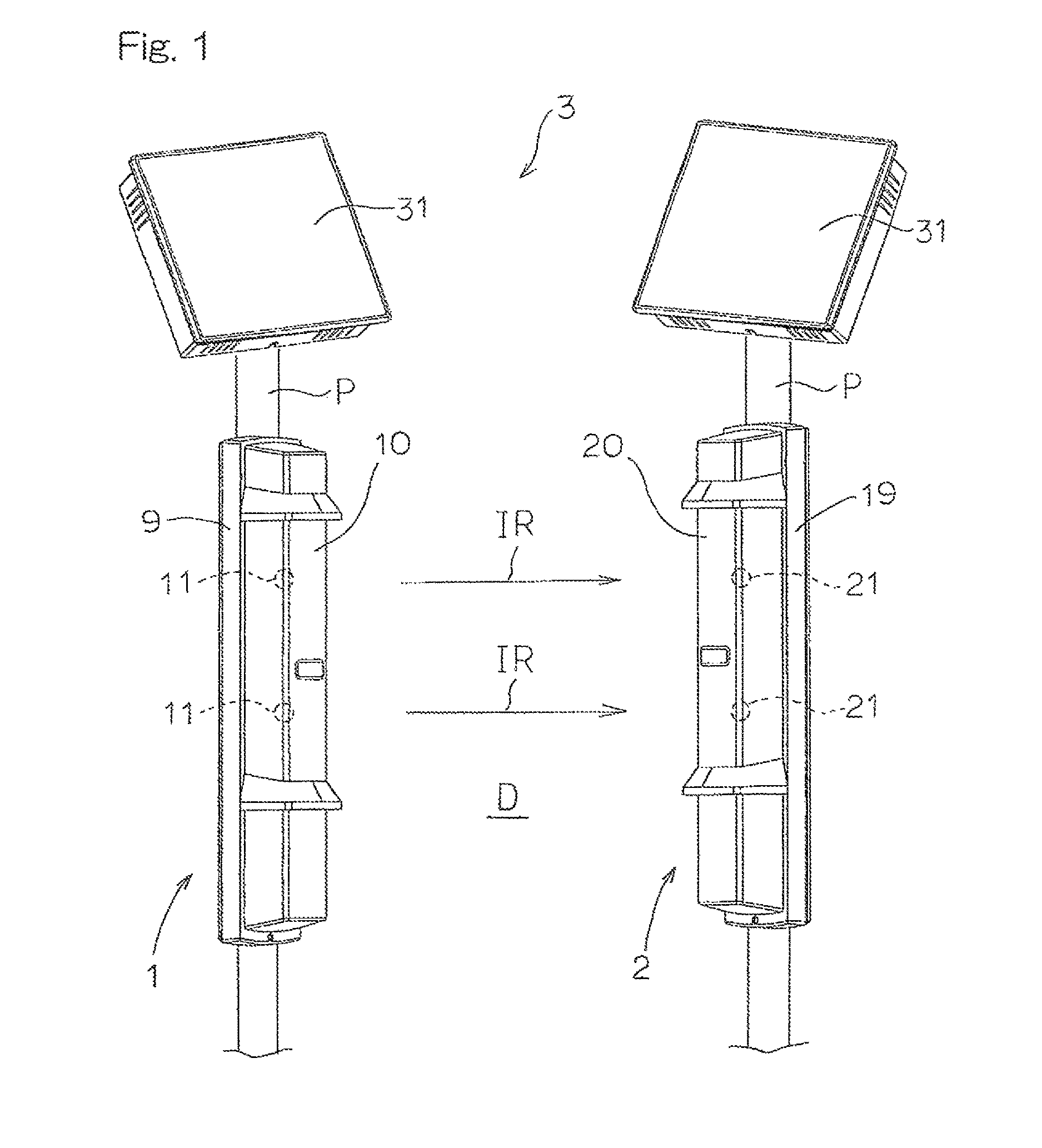
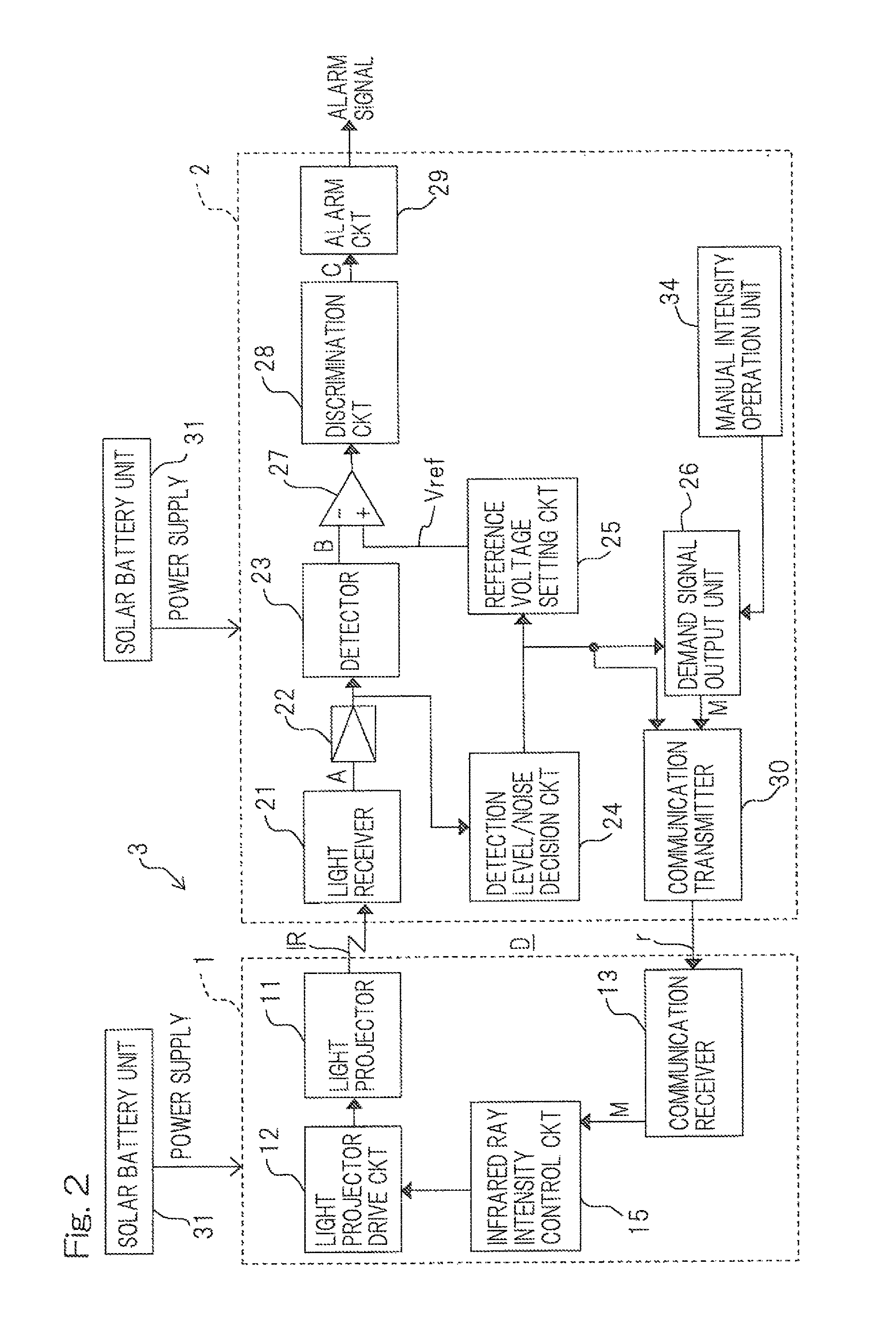
[0019]Hereafter, an embodiment of the present invention will be described with reference to the drawings. FIG. 1 is a perspective view showing a solar battery-driven object detection system according to an embodiment of the present invention. As shown in FIG. 1, the object detection system includes a detection unit 3 having a transmission unit 1 such as a light projecting unit that projects a detection beam such as infrared rays IR to a detection (warning) region D, and a reception unit 2 such as a light receiving unit that receives the projected infrared rays IR so as to detect an object when the object intercepts the infrared rays in the detection region D, and a solar battery unit 31 serving as the power source unit that supplies power to the detection unit 3. In this embodiment, the detection unit 3 is of an active infrared ray (AIR) type, and the object detection system is intended for use in a security sensor installed outdoors and configured to output an alarm signal upon det...


PUM


Abstract

A reception unit 2 of a detection unit 3 includes a transmitter 30 that transmits a reception (detection) level of an infrared beam to a transmission unit 1, and a demand signal output unit 26 that transmits to the transmission unit 1 a demand signal M, demanding to control the intensity of the infrared beam to be transmitted so that the reception level matches a predetermined value. The transmission unit 1 includes an infrared ray (detection beam) intensity control unit 15 that controls, upon receipt of the demand signal M, the intensity of the infrared beam to be transmitted so that the reception level matches the predetermined value. A power source unit 31 is a solar battery unit including a solar panel and a charging medium that stores power from the solar panel.

Description

CROSS REFERENCE TO THE RELATED APPLICATION[0001]This application is based on and claims Convention priority to Japanese patent application No. 2013-058050, filed on Mar. 21, 2013, the entire disclosure of which is herein incorporated by reference as a part of this application.BACKGROUND OF THE INVENTION[0002]Field of the Invention[0003]The present invention relates to a solar battery-driven object detection system, in which a detection unit having a transmission unit and a reception unit is driven by the solar battery unit, the reception unit constantly receives detection beams transmitted from the transmission unit, and thereby detection of an object when the object intercepts the detection beams is achieved.[0004]Description of Related Art[0005]Object detection systems are thus far known that include a detection unit having a transmission unit such as a light projecting unit and a reception unit such as a light receiving unit which are arranged so as to oppose each other across a ...

Claims


Application Information

Patent Timeline
Patent Type & Authority Patents(United States)
IPC IPC(8): G08B13/16G08B1/08G08B21/00G08B13/24H01L31/048H02S20/30H02S40/38H02S10/20G01V8/10
CPCG08B13/2491G01V8/10H01L31/048H02S10/20H02S20/30H02S40/38Y02E10/50Y02E70/30
Inventor MAKINO, HIROSHIHAYASHIDE, KOJIKURATA, MATAICHIIKEDA
Owner OPTEX CO LTD
Learn More