
Battery system

a battery and system technology, applied in the field of batteries, can solve the problems of reducing battery capacity and impaired estimation accuracy, and achieve the effect of rapid reduction of li

Active Publication Date: 2018-04-17
TOYOTA JIDOSHA KK
View PDF15 Cites 0 Cited by
  • Summary
  • Abstract
  • Description
  • Claims
  • Application Information

AI Technical Summary

Benefits of technology

[0007]Accordingly, an object of the present invention is to provide a battery system allowing a battery having moisture having intruded therein to nonetheless have its battery capacity estimated without impaired accuracy.
[0011]The battery's temperature data can be relatively easily obtained, which can help to estimate how much amount of moisture the battery has having intruded therein.
[0013]How much amount of moisture the battery has having intruded therein can thus be obtained with high accuracy.
[0015]Thus, when how much amount of moisture the battery has having intruded therein is considered in obtaining how much battery capacity it has, the battery capacity can be obtained with high accuracy.
[0019]This allows a driver to for example have a dealer exchange the battery with another timely before its lifetime rapidly decreases.

Problems solved by technology

However, when the battery has moisture having intruded therein from the atmosphere or the like, the battery's lithium ions react with the moisture and are thus consumed, resulting in reduced battery capacity.
As a result, the estimated value in battery capacity calculated as described in Japanese Patent Laying-Open No. 2006-250905 has a deviation from the actual battery capacity, resulting in impaired estimation accuracy.

Method used


Image

  • Battery system
  • Battery system
  • Battery system

Examples


first embodiment

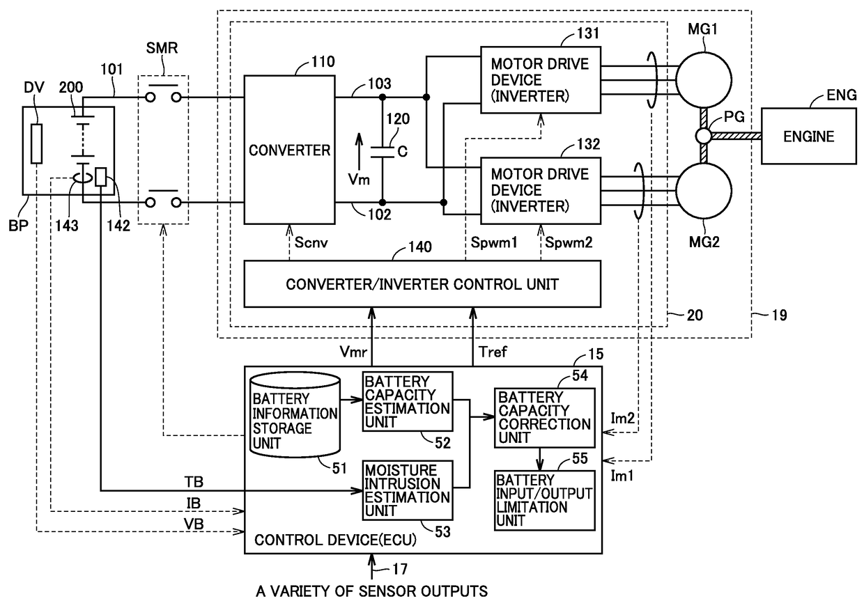
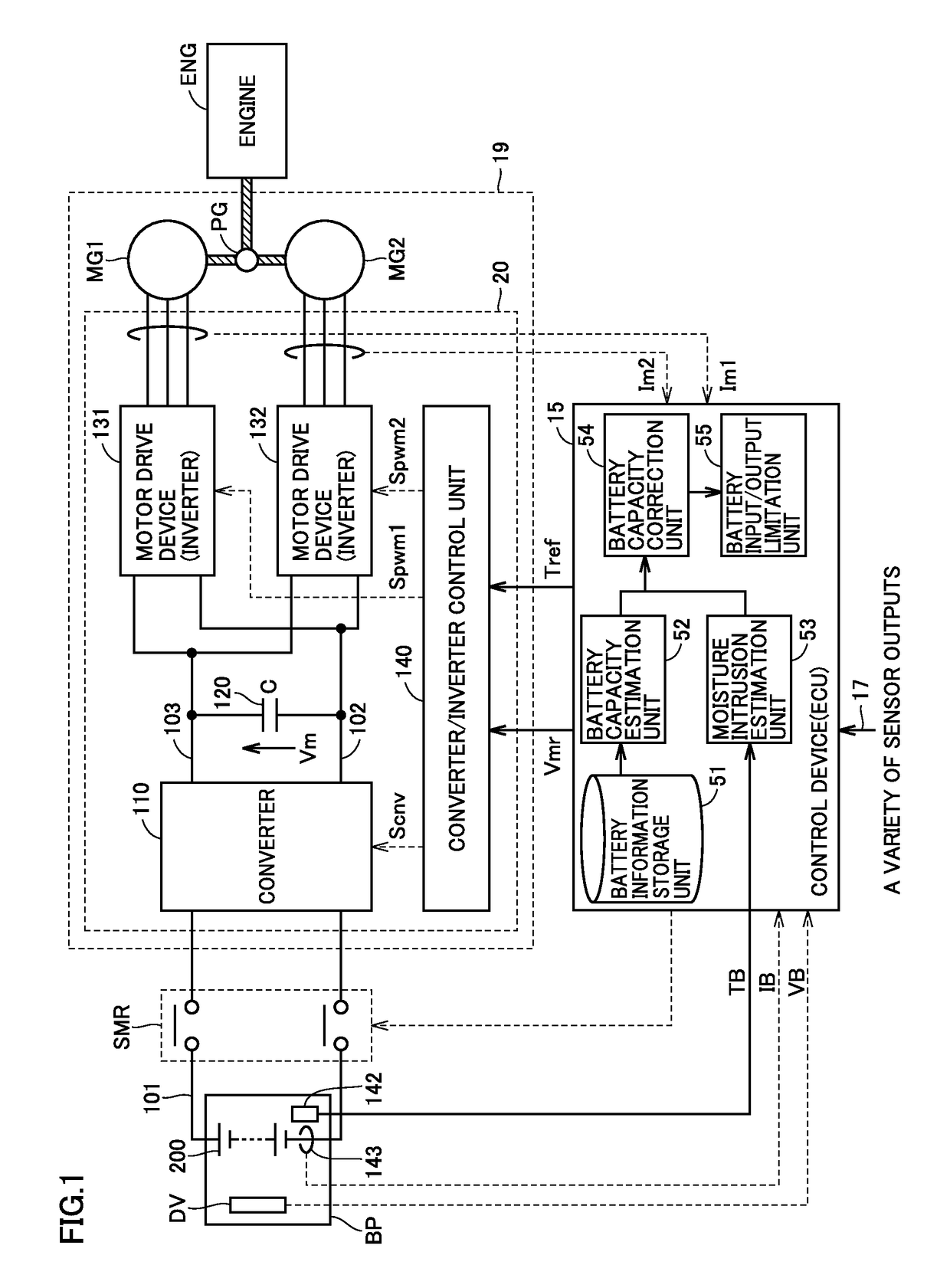
[0032]FIG. 1 is a block diagram showing a configuration of a vehicle having a battery system mounted therein according to a first embodiment of the present invention.

[0033]With reference to FIG. 1, a hybrid vehicle includes a battery pack BP, a system main relay SMR, a charge and discharge unit 19, an engine ENG, and a control device 15.

[0034]Charge and discharge unit 19 charges and discharges battery 200. Charge and discharge unit 19 includes a power control unit (PCU) 20, motor generators MG1 and MG2, and a power split device PG.

[0035]Battery pack BP includes a battery 200, a voltage monitoring unit DV, a temperature sensor 142, and a current sensor 143. Battery 200 includes a plurality of battery cells connected in series.

[0036]Battery 200 is a direct current (dc) power supply, and for example includes a rechargeable battery, such as a nickel metal hydride battery and a lithium ion battery. Battery 200 supplies dc voltage to PCU 20 and is also charged with dc voltage provided fro...

second embodiment

[0075]FIG. 8 shows a configuration of a control device (or ECU) 115 of a second embodiment.

[0076]The FIG. 8 control device 115 differs from the FIG. 1 control device 15 in that the former excludes battery input / output limitation unit 55 and instead includes a notification unit 155.

[0077]A display device 156 is for example a liquid crystal display.

[0078]When a corrected battery capacity is equal to or smaller than the threshold value, notification unit 155 provides information indicating that the battery has a small battery capacity, and display device 156 displays the information.

[0079]FIG. 9 is a flowchart of an operation procedure according to the second embodiment.

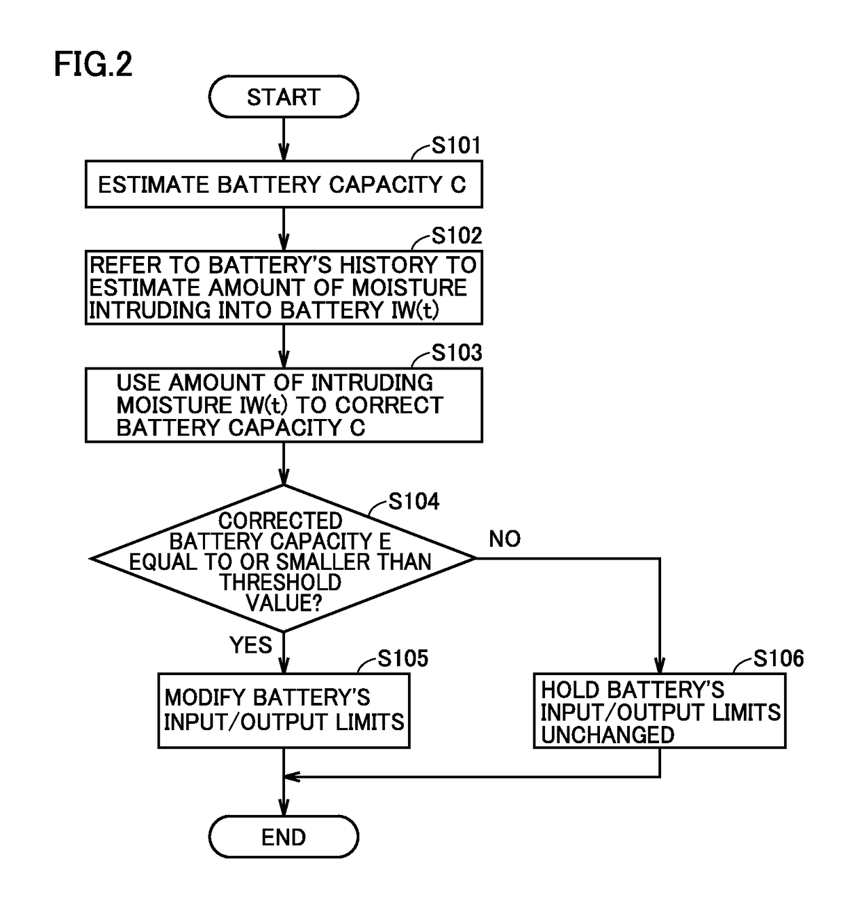
[0080]The FIG. 9 flowchart differs from the FIG. 2 flowchart in that the former excludes Step S105 and Step S106 and instead includes Step S205 and Step S206.

[0081]In step S205, notification unit 155 provides information indicating that the battery has a small battery capacity, and display device 156 displays the inform...


PUM

PropertyMeasurementUnit
temperatureaaaaaaaaaa
battery capacityaaaaaaaaaa
lifetimeaaaaaaaaaa

Abstract

A battery capacity estimation unit estimates a battery in battery capacity based on information regarding the battery's use history. A moisture intrusion estimation unit estimates an amount of moisture intruding into the battery. A battery capacity correction unit uses the estimated amount of intruding moisture to correct the estimated battery capacity.

Description

[0001]This nonprovisional application is based on Japanese Patent Application No. 2014-027562 filed on Feb. 17, 2014, with the Japan Patent Office, the entire contents of which are hereby incorporated by reference.BACKGROUND OF THE INVENTION[0002]Field of the Invention[0003]The present invention relates to a battery system, and for example to a battery system mounted in a vehicle.[0004]Description of the Background Art[0005]Japanese Patent Laying-Open No. 2006-250905 discloses using battery information stored in a database to calculate a battery's degradation factor which is in turn used to estimate a capacity that the battery can provide to store electric power, i.e., battery capacity.SUMMARY OF THE INVENTION[0006]However, when the battery has moisture having intruded therein from the atmosphere or the like, the battery's lithium ions react with the moisture and are thus consumed, resulting in reduced battery capacity. As a result, the estimated value in battery capacity calculated...

Claims


Application Information

Patent Timeline
Patent Type & Authority Patents(United States)
IPC IPC(8): H01M10/48B60L3/12B60L7/14B60L11/14B60L11/12B60L11/18H01M10/052H02J7/00B60L3/04B60L15/20B60L50/15B60L50/16
CPCH01M10/48B60L3/12B60L7/14B60L11/123B60L11/14B60L11/1861B60L11/1864B60L15/2009H01M10/052H01M10/486B60L3/04Y02T10/7275B60L2210/10B60L2210/40B60L2240/12B60L2240/545B60L2240/547B60L2240/549B60L2240/80B60L2250/16B60L2260/44H01M10/488H01M2220/20H02J7/0021Y02T10/6217Y02T10/645Y02T10/7005Y02T10/7044Y02T10/7061Y02T10/7077Y02T10/7216Y02T10/7241B60L50/61B60L50/16B60L58/12B60L58/21Y02E60/10Y02T10/62Y02T10/64Y02T10/70Y02T10/72Y02T10/7072H02J7/0048H02J7/005H02J7/0013
Inventor NAKAYAMA, HIROYUKINAKASHIMA, MAKOTOKOMATSUKI, MASATOKURIMOTO, YASUHIDE
Owner TOYOTA JIDOSHA KK
Learn More