
Storage battery, control method of storage battery, control device, and control method

a storage battery and control method technology, applied in the direction of transportation and packaging, secondary cell servicing/maintenance, electrochemical generators, etc., can solve the problems of storage battery exchange with a new storage battery, charge timing becomes faster, etc., and achieve the effect of suppressing battery capacity deterioration

Inactive Publication Date: 2017-09-26
NEC CORP
View PDF10 Cites 2 Cited by
  • Summary
  • Abstract
  • Description
  • Claims
  • Application Information

AI Technical Summary

Benefits of technology

The invention provides a technology to prevent battery capacity deterioration when using a storage battery in a harsh temperature environment. This technology allows the battery to complete its charge at a low SOC level, reducing deterioration compared to a normal temperature environment. However, when used in a harsh temperature environment, the technology allows the battery to reach a full-charge state faster, reducing the likelihood of replacing the battery with a new one prematurely. Overall, this technology helps to maintain the battery's performance and lifespan in challenging environments.

Problems solved by technology

After using the storage battery in a normal temperature environment, the storage battery is used in a harsh temperature environment, and a user who perceives a difference between these charge timings may erroneously assume that the charge timing becomes faster because deterioration of the storage battery progresses.
As a result thereof, a disadvantage that even though the storage battery is able to be still used, the storage battery is exchanged with a new storage battery may occur.

Method used


Image

  • Storage battery, control method of storage battery, control device, and control method
  • Storage battery, control method of storage battery, control device, and control method
  • Storage battery, control method of storage battery, control device, and control method

Examples


first embodiment

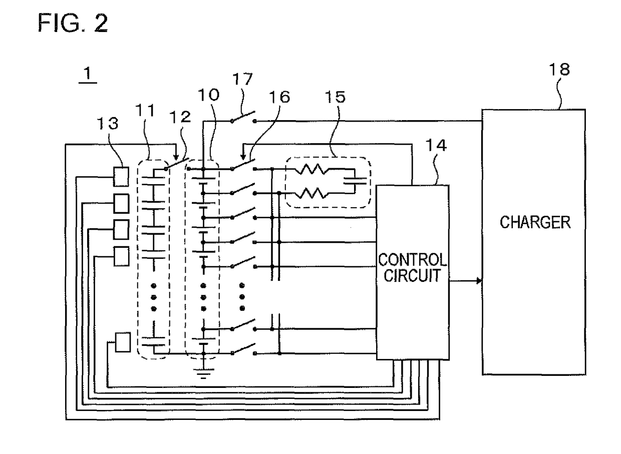
[0055]This embodiment is an embodiment in which the storage battery 1 of the first embodiment is more specified. In FIG. 2, an example of the configuration of the storage battery 1 of this embodiment is illustrated.

[0056]As illustrated, the storage battery 1 includes the electric storage unit 10, the auxiliary electric storage unit 11, a switch 12, the temperature measurement unit 13, the charge and discharge control unit (a control circuit) 14, a balance circuit 15, a switch 16, and a switch 17. The storage battery 1 is connected to a charger 18 through an external connection terminal for charge and discharge.

[0057]The electric storage unit 10 has a configuration in which a plurality of lithium ion secondary battery cells are connected in series. The energy density of the electric storage unit 10, for example, is able to be greater than or equal to 100 Wh / kg.

[0058]The auxiliary electric storage unit 11 has a configuration in which a plurality of capacitor cells (an electric double ...

second embodiment

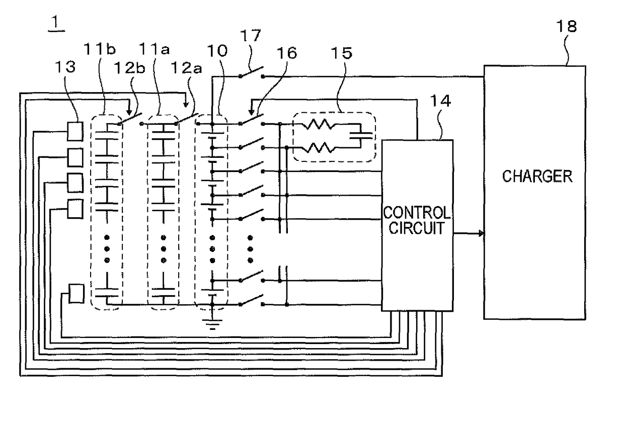
[0083]The electric storage unit 10, the temperature measurement unit 13, the balance circuit 15, the switch 16, and the switch 17 are identical to those of the

[0084]The auxiliary electric storage unit 11 includes two rows of the sub-auxiliary electric storage units 11a and 11b. Each of the sub-auxiliary electric storage units 11a and 11b is configured of a plurality of capacitor cells (an electric double layer capacitor cell or the like) connected in series. Then, the plurality of sub-auxiliary electric storage units 11a and 11b are connected to each other in parallel. In addition, the plurality of sub-auxiliary electric storage units 11a and 11b are connected to the electric storage unit 10 in parallel. The plurality of sub-auxiliary electric storage units 11a and 11b is configured to control on / off of each of the switches 12a and 12b, and thus to enable a connection state with respect to the external connection terminal for charge and discharge to be individually controlled. The e...


PUM

PropertyMeasurementUnit
temperatureaaaaaaaaaa

Abstract

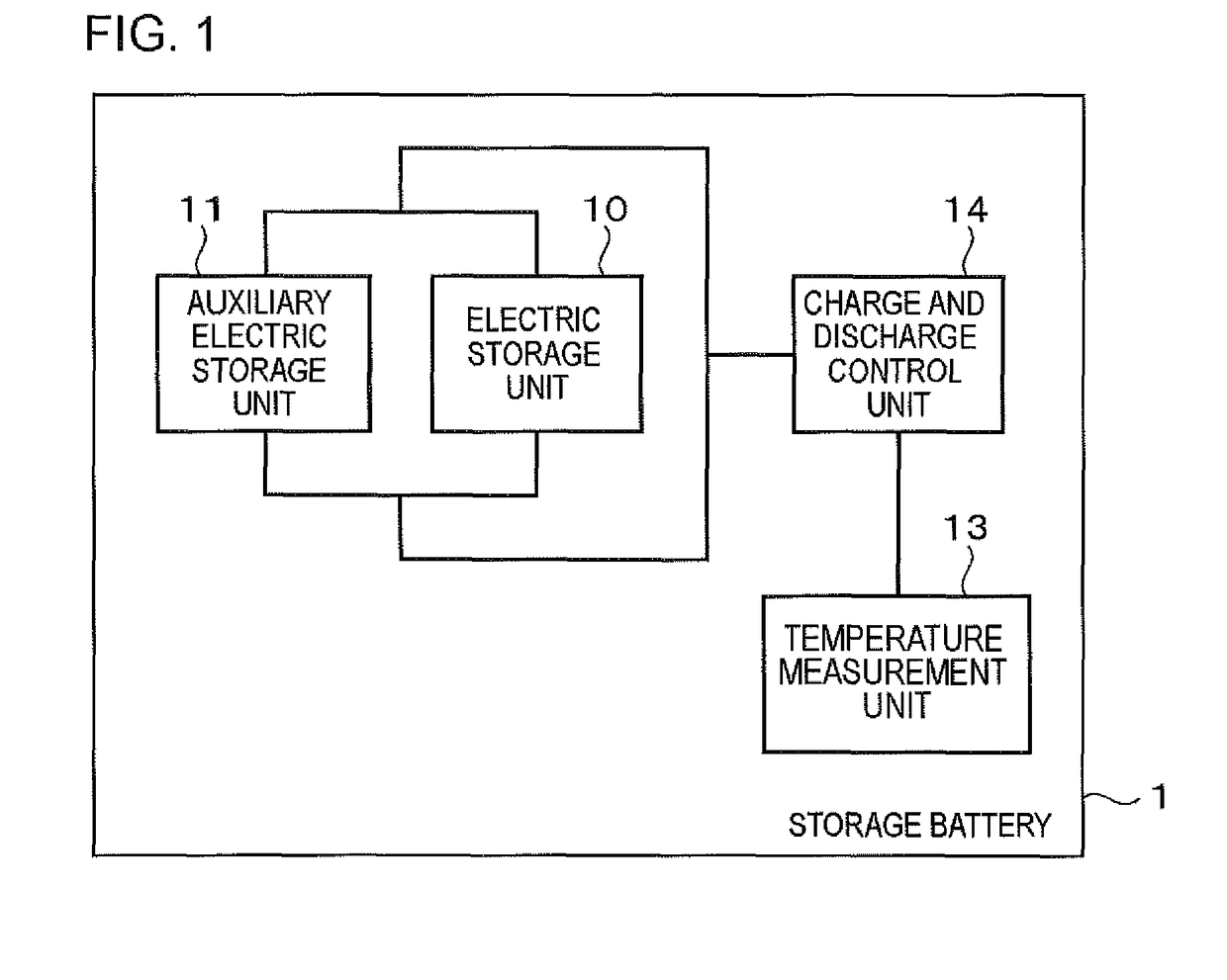
A storage battery (1) including an electric storage unit (10), an auxiliary electric storage unit (11) connected to the electric storage unit (10) in parallel, a temperature measurement unit (13) measuring a temperature, and a charge and discharge control unit (14) controlling charge and discharge of the electric storage unit (10) and the auxiliary electric storage unit (11), in which the charge and discharge control unit (14) changes an SOC (a charge completion SOC) of the electric storage unit (10) and the auxiliary electric storage unit (11) in a charge completion state of not allowing any more charge according to a measurement result of the temperature measurement unit (13), increases the charge completion SOC of the auxiliary electric storage unit (11) when the charge completion SOC of the electric storage unit (10) decreases, and decreases the charge completion SOC of the auxiliary electric storage unit (11) when the charge completion SOC of the electric storage unit (10) increases.

Description

[0001]This application is a National Stage Entry of PCT / JP2014 / 054701 filed on Feb. 26, 2014, which claims priority from Japanese Patent Application 2013-037861 filed on Feb. 27, 2013, the contents of all of which are incorporated herein by reference, in their entirety.TECHNICAL FIELD[0002]The present invention relates to a storage battery, a control method of a storage battery, a control device, and a control method.BACKGROUND ART[0003]When a storage battery such as a lithium ion secondary battery or a lead storage battery is placed in a charge state in a harsh temperature environment, battery capacity deterioration easily progresses. In particular, the battery capacity deterioration is remarkable in a full-charge state where a state of charge (SOC) is 100% (refer to FIGS. 7 and 8). For this reason, it is preferable that the storage battery is used in a mild temperature environment (in a normal temperature environment), for example, approximately from −10° C. to 50° C.[0004]In Pate...

Claims


Application Information

Patent Timeline
Patent Type & Authority Patents(United States)
IPC IPC(8): H01M10/44H01M10/42H01M10/48H02J7/00H01M10/46
CPCH01M10/443H01M10/425H01M10/441H01M10/46H01M10/486H02J7/007H02J7/0054H02J7/0075H01M2010/4271H02J7/0069H02J7/342Y02E60/10
Inventor MATSUNAGA, KOJIKAJITANI, HIROSHIONOSE, KATSUYA
Owner NEC CORP
Learn More