
Systems and Methods for Protecting a Cut End of an Electrical Conductor

Inactive Publication Date: 2016-01-14
SUPER SEAL
View PDF1 Cites 2 Cited by
  • Summary
  • Abstract
  • Description
  • Claims
  • Application Information

AI Technical Summary

Benefits of technology

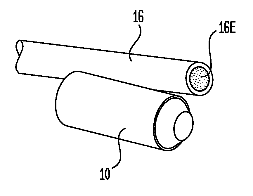
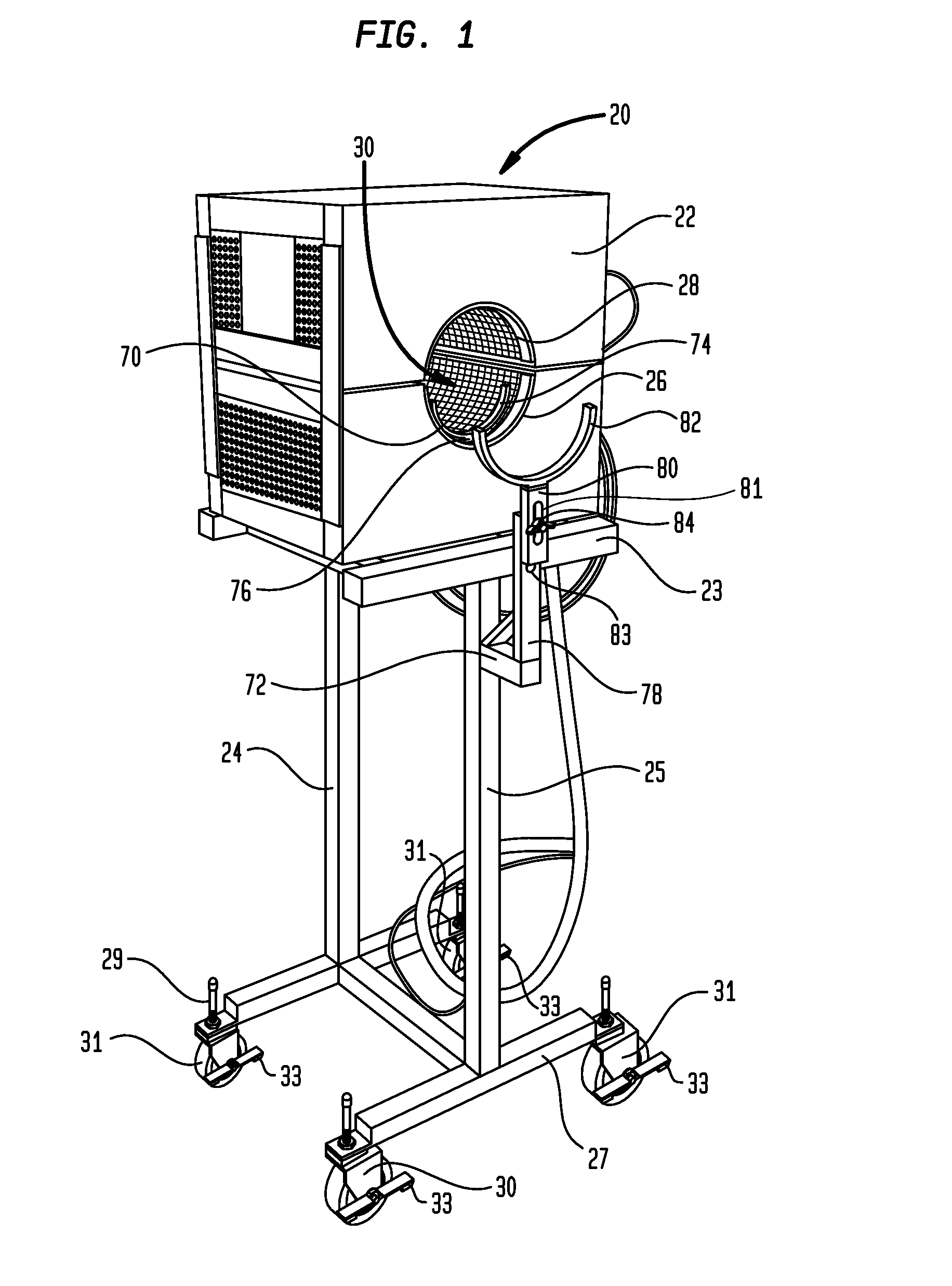
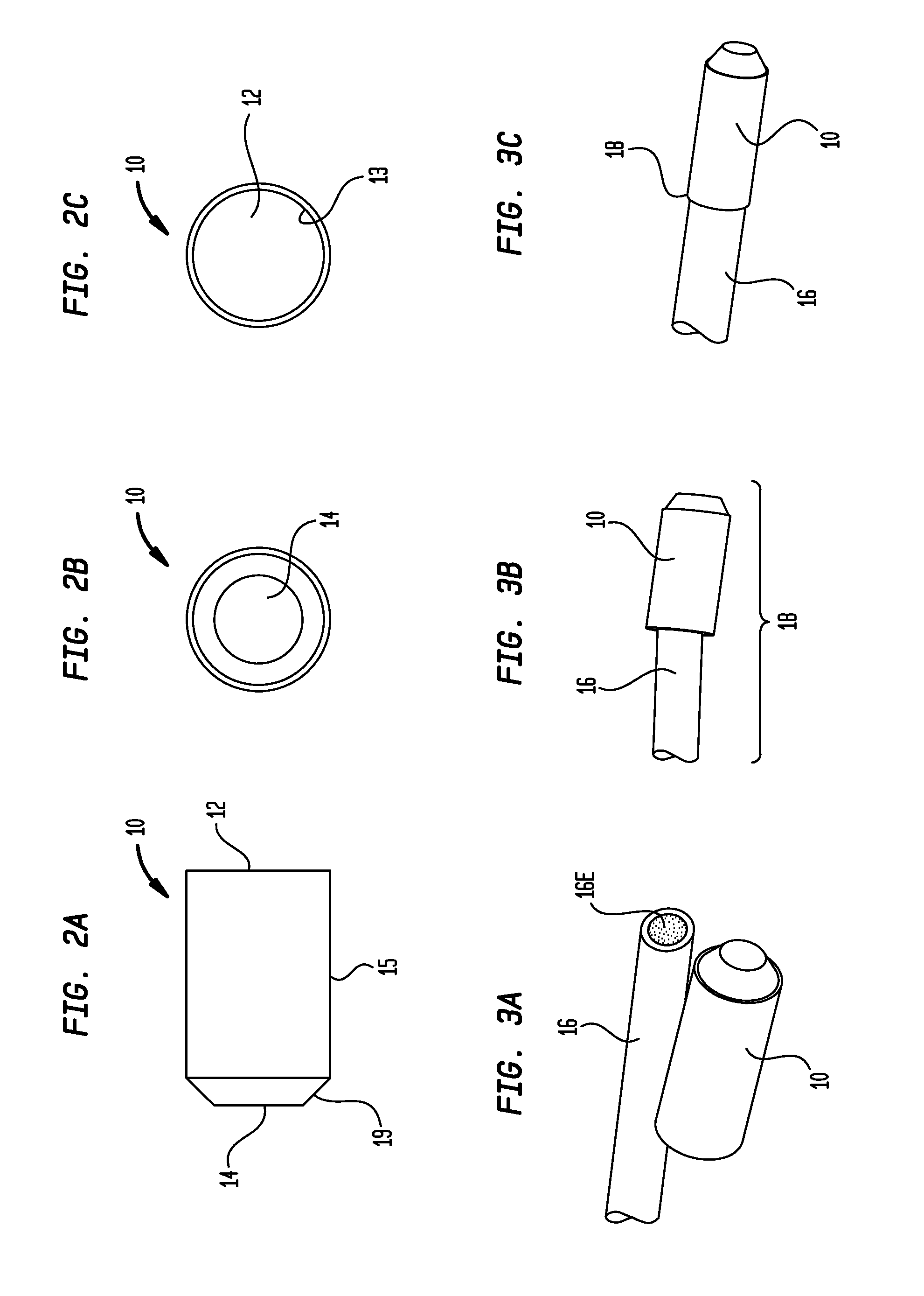
The present invention provides a system for protecting the end of a cut electrical conductor by sealing it using a heat-shrinkable end cap and an end cap installation apparatus. The system includes a housing, a heating chamber, a control panel, and a temperature sensing device. The method involves positioning the end cap in the heating chamber, setting the temperature setpoint, and shrinking the end cap onto the end of the cut electrical conductor. The resulting system and method provide a reliable and effective way to protect the end of a cut electrical conductor.

Problems solved by technology

Holding the heat gun and trying to apply the heat evenly to the end caps is tedious and time-consuming.
Many work environments prohibit the use of an open flame such as a propane torch for safety reasons.
The heat gun and torch do not always apply heat uniformly and how much heat is being applied generally cannot be determined.

Method used


Image

  • Systems and Methods for Protecting a Cut End of an Electrical Conductor
  • Systems and Methods for Protecting a Cut End of an Electrical Conductor
  • Systems and Methods for Protecting a Cut End of an Electrical Conductor

Examples


Embodiment Construction

[0020]Certain terminology may be used in the following description for convenience only and is not limiting. The words “lower” and “upper” and “top” and “bottom” designate directions in the drawings to which reference is made. The terminology includes the words above specifically mentioned, derivatives thereof and words of similar import.

[0021]Where a term is provided in the singular, the inventors also contemplate aspects of the invention described by the plural of that term. As used in this specification and in the appended claims, the singular forms “a”, “an” and “the” include plural references unless the context clearly dictates otherwise, e.g., “a heater” may include a plurality of heaters. Thus, for example, a reference to “a method” includes one or more methods, and / or steps of the type described herein and / or which will become apparent to those persons skilled in the art upon reading this disclosure.

[0022]Unless defined otherwise, all technical and scientific terms used here...


PUM


Abstract

Systems and methods for protecting a cut end of an electrical conductor via the use of an end cap and an end cap attachment apparatus. The end cap attachment apparatus easily and quickly heat shrinks the end cap onto the electrical conductor, thereby sealing the end. The system comprises a heat-shrinkable end cap and an end cap installation apparatus. The end cap is placed over the cut end of electrical conductor. The apparatus comprises an inner heating chamber controlled through a control panel. The end cap installation apparatus applies heat evenly and rapidly to shrink and seal the end cap onto the cut end. The method comprises placing the cut end of the electrical conductor surrounded by an unshrunken end cap into the heating inner chamber for a sufficient time to shrink the end cap onto the end of the electrical conductor and then removing.

Description

CROSS-REFERENCE TO RELATED APPLICATIONS[0001]This application claims the benefit of the U.S. provisional patent application entitled “Systems and Methods for Protecting a Cut End of Wire,” having Ser. No. 62 / 023,720, filed Jul. 11, 2014, which is hereby incorporated by reference in its entirety as if fully set forth herein.BACKGROUND OF THE INVENTION[0002]Embodiments in the present disclosure generally relate to systems and methods for protecting a cut end of an electrical conductor. More specifically, the present disclosure relates to systems and methods for protecting a cut end of an electrical conductor such as a wire, cable, or the like via the use of an end cap and an end cap attachment apparatus. However, alternate embodiments of the present invention are envisioned in which the end cap installation apparatus is utilized to seal the end of objects other than electrical conductors including, without limitation, pipe, conduit, tubing, and wood.[0003]Cut ends of electrical conduc...

Claims


Application Information

Patent Timeline
IPC IPC(8): H01R43/04H01R4/22
CPCH01R4/22H01R43/04H01R4/72
Inventor NEWBAUER, III, WILLIAM, E.
Owner SUPER SEAL
Learn More