Cageway connecting device and connecting method thereof

a technology of connecting device and cageway, which is applied in the direction of mine lifts, mining structures, elevators, etc., can solve the problems of difficult to ensure the installation accuracy of the cageway, the adjustment range of the cageway is very small, and the adjustment method is limited, so as to improve the stability of the device, strengthen the firmness and stability of the overall structure, and lower the cageway

Active Publication Date: 2021-12-14
HEFEI DESIGN & RES INST OF COAL IND CO LTD +2
View PDF16 Cites 0 Cited by
  • Summary
  • Abstract
  • Description
  • Claims
  • Application Information

AI Technical Summary

Benefits of technology

[0008]Therefore, the object of the present invention is to provide a cageway connecting device, which can connect multiple cageways conveniently.
[0053]In the connecting method of the present invention, in step (1), making one-to-one corresponding marks on each cageway connecting device and the corresponding cageways, and protecting the ends of the cageways.
[0055]Solution of the present invention, for solving the above problem, is that apply the cageway connecting device which can connect multiple cageways conveniently. Each cageway connecting device can connect one upper cageway and one lower cageway, so multiple cageways can be connected, and the notch is set at the top end of the lower cageway, so that the lower cageway is convenient to insert into the cageway connecting device. The two first steel angles can clamp the corresponding first cageway beam, so as to make each cageway connecting device be fixed on the corresponding first cageway beam, and further fix the upper cageway and the lower cageway. In this way, it is convenient to adjust the installation position of the cageway connecting device, and then adjust the installation position of the upper and lower cageways. The fixed block, the pin boss and the fixed pin can fix the cageway connecting device and the lower cageway to enhance the stability of the device and the lower cageway, and further the shim and ribs plate are able to strengthen the firmness and stability of the overall structure.
[0056]Moreover, the cageway connecting device of the present invention is independent of each cageway, and each cageway connecting device is set between the two cageways, therefore, the device can be installed and adjusted freely and accurately on the cageway beam. The position accuracy of the cageways is determined by multiple cageway connecting devices as a whole, which can improve the accuracy of the initial installation of the cageway and facilitate the replacement of the cageway. Furthermore, the connecting method of the present invention makes each first cageway beam bear the weight of the above cageway, so the first cageway beam is determined and controllable, and the deformation of the first cageway beams and the mutual extrusion of the cageways will not exist.
[0057]In addition, the assist mechanism further strengthens the stability of the upper cageway and the lower cageway, prevents the offset of each cageway, and further improves the stability of the connection of the cageways. The fixed pin can be a taper pin, its self-locking property is good, and the positioning accuracy is high, which is convenient for the installation of the cageway and the influence of multiple assembly and disassembly on the positioning accuracy is small. The fixed pin can be a cylindrical pin, the shear resistance between the upper cageway and the lower cageway can be strengthened, and the stability of the connection of the cageways can be improved.

Problems solved by technology

However, there are some disadvantages in traditional cageway structure connection mode, and they are as follows.
(1) It is not easy to ensure the installation accuracy of the cageway.
Because the installation accuracy of the cageway is adjusted by the cageway beam, once the cageway beam is fixed, the adjustment range of the cageway is very small, and the adjustment method is limited.
In addition, two or more cageways are often fixed on one cageway beam, and the position of each cageway cannot be adjusted.
There is extrusion relationship between adjacent cageways, which also has a negative impact on the installation accuracy.
There are two ways to connect the upper and lower cageways, one is direct butt joint, which has less mutual interference between the upper and lower cageways, but there is dislocation between the cageways, which is very harmful to the overall quality improvement of the cageway, and many new mines are no longer used.
The upper and lower cageways of the two ways transfer forces to each other, and these forces are uncontrollable, especially when multiple cageways transfer forces together downward, which may cause deformation of the lower cageway beam and cageways.
(3) It is not conducive to the maintenance and adjustment of cageway.
After the hoisting system runs for a period of time, the shaft wall will settle and deform, or the cageway beam and the cageways are damaged, so it is necessary to adjust the position of the cageway and the cageway beam.
In the traditional structure, because the upper and lower cageways are squeezed together, it is difficult to adjust.
(4) It is not conducive to replace cageway.
When reinstalling another cageway, because the position cannula cannot be inserted, it can only be simply connected, and there is a great possibility of dislocation between cageways, thus reducing the quality of the overall cageway.
If the straightness, smoothness and flatness of the whole cageway cannot meet the technical requirements, the maintenance and repair conditions cannot be guaranteed, and the requirements for high speed and heavy load of the lifting system cannot be achieved.

Method used


Image

  • Cageway connecting device and connecting method thereof
  • Cageway connecting device and connecting method thereof
  • Cageway connecting device and connecting method thereof

Examples


first embodiment

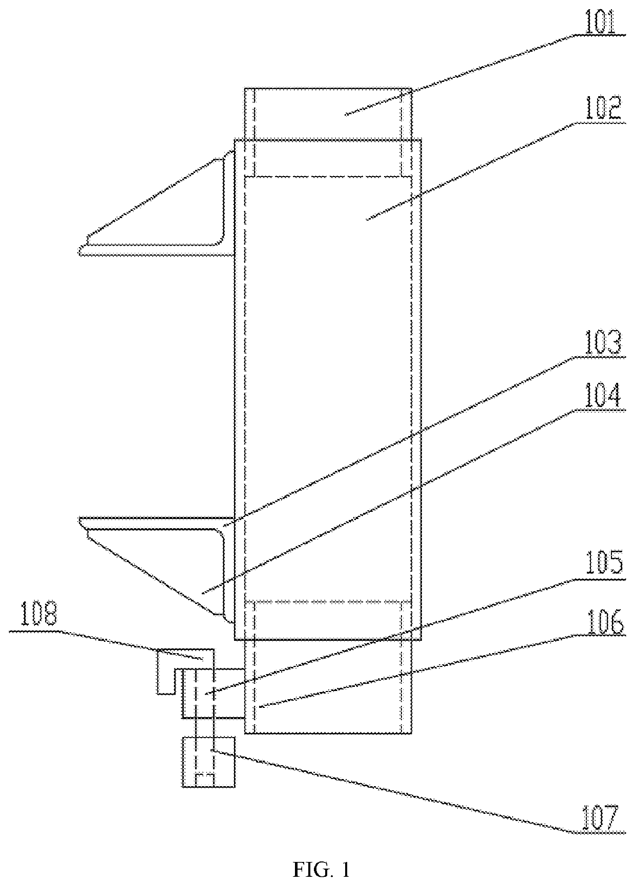
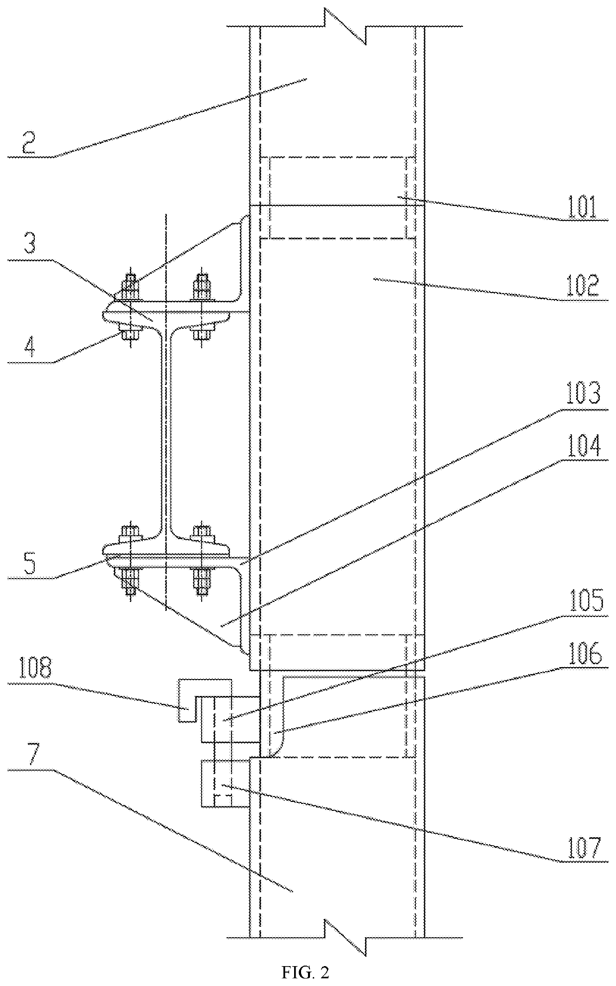
[0064]Referring to FIGS. 1 and 2, a cageway connecting device is shown as an embodiment. The cageway connecting device of this embodiment is set between two cageways, and for the convenience of description, the two cageways are named upper cageway 2 and lower cageway 7, the device is used for connecting the upper cageway 2 and the lower cageway 7. The cageway connecting device includes a connecting cageway 102, an upper cannula 101, a lower cannula 106, two first steel angles 103, a fixed block 105, a pin boss 107, a fixed pin 108, and further includes two ribs 104. Wherein, if the cageway connecting device is separated separately, the guiding function and positioning function of the traditional cageway are respectively undertaken by each cageway and the corresponding cageway connecting device in the embodiment.

[0065]The connecting cageway 102 is set between the upper cageway 2 and the lower cageway 7, and the cross section of the connecting cageway 102 is the same as that of the up...

second embodiment

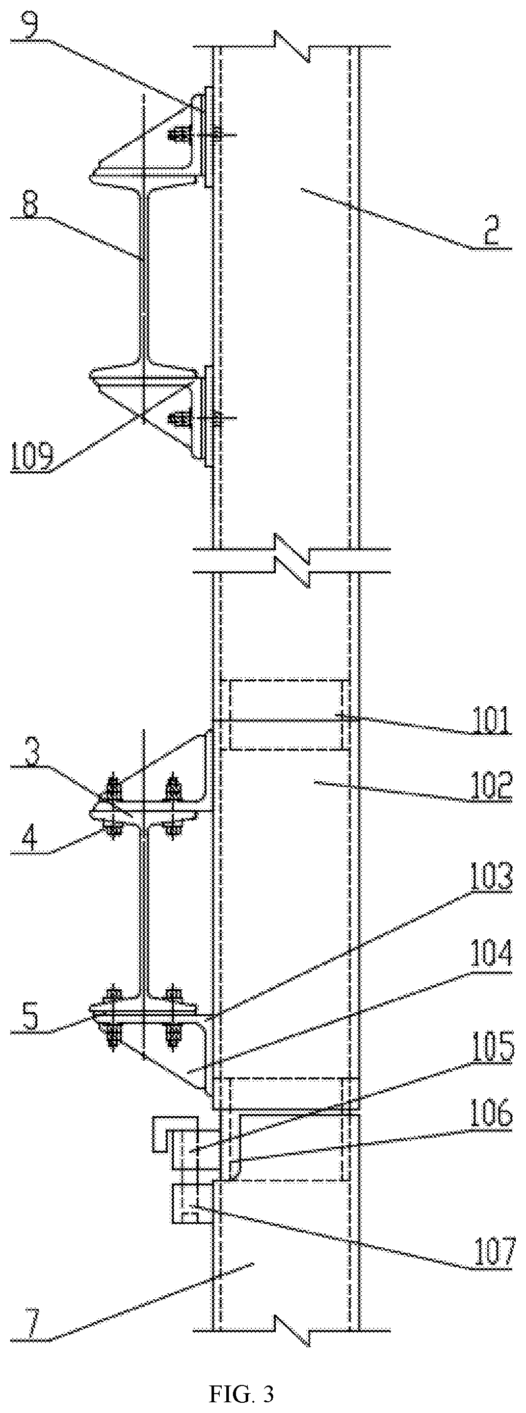
[0077]A connecting method of a cageway connecting device is shown as an embodiment. The method is used for connecting an upper cageway 2 and a lower cageway 7, and a notch being set at the top end of the lower cageway 7. The cageway connecting device of this embodiment is the same as that of the first embodiment. The connecting method includes the following steps: (1) Fixing the two first steel angles 103 in the vertical direction, and putting the top end of the lower cageway 7 on the bottom end of the lower cannula 106, then rotating the lower cageway 7 to make the first pin bore and the second pin bore be coaxial; (2) Passing the bottom end of the fixed pin 108 through the first pin bore, then inserting the bottom end of the fixed pin 108 into the second pin bore to make the pin boss 107 and the fixed block 105 be fixed; and (3) Putting the bottom end of the upper cageway 2 on the top end of the upper cannula 101 to make upper cageway 2 be overlapped on the connecting cageway 102....

third embodiment

[0079]A connecting method of a cageway connecting device is shown as an embodiment. The method is used for connecting an upper cageway 2 and a lower cageway 7, and a notch being set at the top end of the lower cageway 7. The cageway connecting device of this embodiment is the same as that of the first embodiment. The connecting method includes the following steps.

[0080](1) Pre assembling each cageway connecting device and the corresponding cageways. In this step, making one-to-one corresponding marks on each cageway connecting device and the corresponding cageways, and protecting the ends of the cageways.

[0081](2) Clamping the first steel angles 103 of each cageway connecting device to the corresponding first cageway beam 3 to make each cageway connecting device be fixed on the corresponding first cageway beam 3. In this step, putting the top end of the lower cageway 7 on the bottom end of the corresponding lower cannula 106 by a bottom-up installation method.

[0082](3) First, puttin...


PUM


Abstract

A cageway connecting device and connecting method thereof is invented, the device includes a connecting cageway, an upper cannula, a lower cannula, two first steel angles, a fixed block, a pin boss and a fixed pin. The connecting cageway is set between the upper cageway and the lower cageway. The upper cannula is fixed in the connecting cageway. The lower cannula is fixed in the connecting cageway. The two first steel angles are fixed on the connecting cageway. The fixed block is fixed on the upper cannula. The pin boss is fixed on the lower cageway. The fixed pin is passed through the first pin bore and inserted into the second pin bore. The invention improve the accuracy of the initial installation of the cageway and facilitate the replacement of the cageway. The first cageway beam is determined and controllable.

Description

FIELD OF THE INVENTION[0001]The present invention relates to technical field of mining equipment technology, and more particularly to a cageway connecting device and connecting method thereof.BACKGROUND OF THE INVENTION[0002]In the vertical shaft hoisting system in the field of mine, when the hoisting container is running up and down, the roller lug on the hoisting container is required to guide the movement in the vertical direction of the cageway, so as to ensure that the hoisting container does not swing in the horizontal direction and ensure the safety of the hoisting system. At present, many cageways (about 12 meters each) made by cold-rolled square steel are used, one by one from the head to the bottom of the mine to form a complete cageway with a length of several hundred meters or more. Each cageway is connected with the first cageway beam through the first steel angle, and the first cageway beam is connected with the shaft again and again. However, there are some disadvanta...

Claims


Application Information

Patent Timeline
Patent Type & Authority Patents(United States)
IPC IPC(8): B66B19/00E21D7/02B66B7/02
CPCE21D7/02B66B7/026B66B19/002
Inventor QIN, QIANGYAN, HONGXINHU, CHANGHUADU, QINGYONGDING, JIANGUO
Owner HEFEI DESIGN & RES INST OF COAL IND CO LTD
Why Eureka
Try Eureka