Joining lined pipe sections

a technology of lined pipes and joints, applied in the direction of rigid pipes, corrosion prevention, coatings, etc., can solve the problem of heat damage to the end of a liner

Active Publication Date: 2021-06-29
PIONEER LINING TECH
View PDF32 Cites 0 Cited by
  • Summary
  • Abstract
  • Description
  • Claims
  • Application Information

AI Technical Summary

Benefits of technology

[0019]Preferably, an insulatory sleeve is provided in a section of lined pipe by locating the insulatory sleeve in an end of the host pipe, temporarily reducing the diameter of the lining and drawing it through the host pipe and the insulatory sleeve, and allowing the lining to revert to form a tight fit against internal surfaces of the host pipe and insulatory sleeve.
[0028]Most preferably, the insulatory sleeve does not extend the full length of the section of lined pipe. Provision of a discrete insulatory sleeve provides thermal protection in the area where it is needed most—i.e. close to the weld and the heat produced thereby—without the expense and technical considerations required to insulate an entire lined pipe section.
[0029]Most preferably, the insulatory sleeves provided in each of the two sections of lined pipe extend beyond respective ends of the pipe linings. Accordingly, the ends of the pipe linings are protected from the potential risk of heat damage.
[0033]In this way, in addition to protecting the ends of the pipe linings from the potential risk of heat damage, the welds produced between the electrofusion fitting and the pipe linings are also protected from the potential risk of heat damage.
[0035]Similarly, in addition to protecting the ends of the pipe linings and / or the electrofusion welds from the potential risk of heat damage when the ends of the host pipes are welded together, they are protected from the potential risk of heat damage when the field joint coating is applied.

Problems solved by technology

A lined pipe comprises a host pipe and a liner; there is a potential risk of heat damage to the ends of a liner when sections of lined pipe are welded together and / or FBE coated which is reduced or removed by providing an insulatory sleeve between the host pipe and liner.

Method used


Image

  • Joining lined pipe sections
  • Joining lined pipe sections

Examples


Embodiment Construction

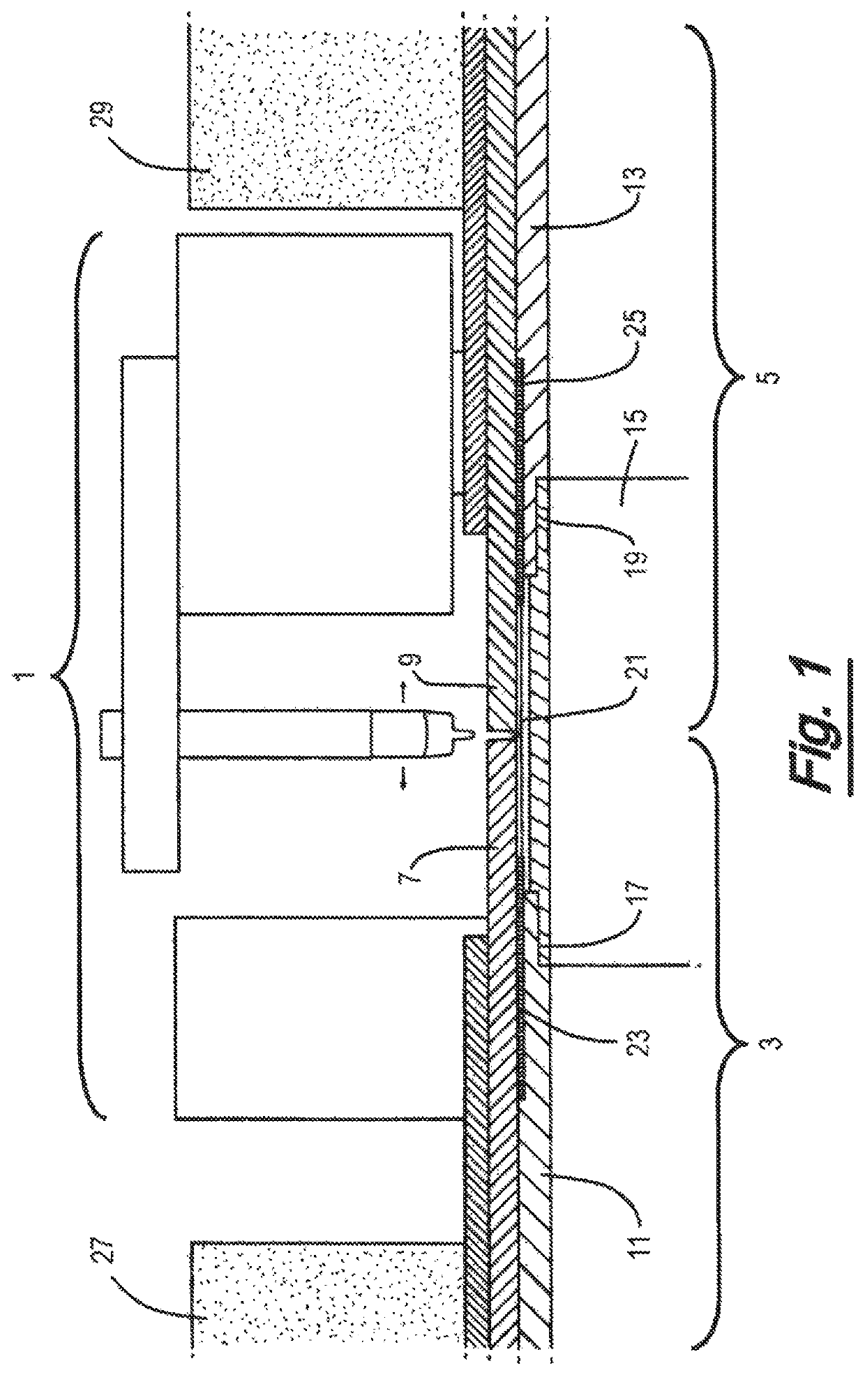
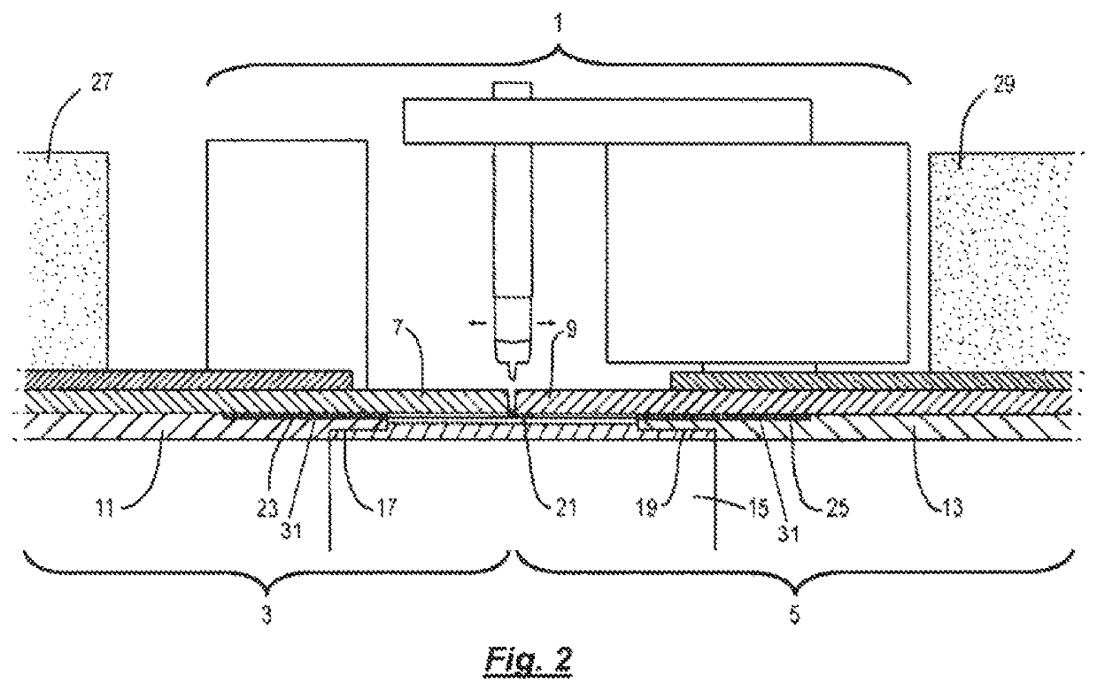
[0061]As discussed in the background to the invention above, automatic welding over polymer lined flowlines has not been employed to date at least partly due to concerns regarding potential damage to the polymer liners. An embodiment of an aspect of the present invention is now described with reference to FIGS. 1 and 2 which reduces the risk of damage to the polymer liners from the heat generated when the ends of line pipe sections are welded together. This is achieved without requiring the use of extension pieces, and enables electrofusion fittings, such as the Applicant's LinerBridge® fitting (in which the end of the polymer liner can be closer to the end of the pipe than in prior arrangements) to be deployed with improved confidence in s-lay and j-lay operations.

[0062]FIG. 1 illustrates a pipe welding process about to commence in which a bug and band type automatic welding tool 1 will perform a girth weld between the end of a first lined pipe section 3 and a second lined pipe sec...


PUM

PropertyMeasurementUnit
lengthsaaaaaaaaaa
lengthsaaaaaaaaaa
diameteraaaaaaaaaa

Abstract

In order to reduce or remove the potential risk of heat damage in the absence of cooling jackets when joining lined pipe sections, each lined pipe section is provided with an insulatory sleeve which is disposed between the host pipe and the respective liner. The sleeves provide discrete thermal protection to the ends of the liners and, where applicable, electrofusion welds between an electrofusion fitting and the liners. The sleeves are first located in the ends of the host pipes which are then lined by drawing the liners through the host pipes via a reduction die to reduce their external diameter. The liners are then reverted towards their original dimensions resulting in a tight fitting against the internal surface of the host pipes and of the insulatory sleeves thereby compressing the insulation material.

Description

[0001]The present invention relates to methods of joining lined pipe sections. More specifically, the present invention concerns improvements to methods of joining lined pipe sections which reduces the risk of damage to the liners from the heat generated when the ends of lined pipe sections are welded together.BACKGROUND TO THE INVENTION[0002]The life and performance of new and existing pipelines can be extended and optimised by lining lengths of metal pipe with polymer liners. Techniques such as the Applicant's Swagelining® pipe lining service allows existing pipelines to be remediated and new pipelines to be provided with corrosion resistance by installing a polymer liner that remains in tight contact with the inside of a host pipe.[0003]Prior to their insertion in a host pipe, the polymer liner pipes have a larger outer diameter than the inner diameter of the host pipe into which they are being inserted. The liner pipes are temporarily reduced in diameter immediately prior to ins...

Claims


Application Information

Patent Timeline
Patent Type & Authority Patents(United States)
IPC IPC(8): F16L13/02F16L1/18F16L59/20F16L58/18
CPCF16L13/0263F16L1/18F16L13/0272F16L58/181F16L59/20F16L9/147F16L9/18F16L58/1045
Inventor BARNES, STEPHEN
Owner PIONEER LINING TECH
Why Eureka
Try Eureka