System and Method for Manually Selecting and Deselecting Devices to Charge in a Wireless Power Network

a wireless power network and wireless technology, applied in the field of wireless power transmission, can solve the problems of increasing the burden on users, increasing the cost of electric energy, and tedious activities,

Active Publication Date: 2016-01-14
ENERGOUS CORPORATION
View PDF6 Cites 244 Cited by
  • Summary
  • Abstract
  • Description
  • Claims
  • Application Information

AI Technical Summary

Benefits of technology

[0012]The wireless power network may further include a wireless power application. The wireless power manager may be a software application, which may be hosted in a computing device, which may be either a local or cloud-based physical or virtual server, or a mobile or hand-held or wearable computing device such as a smart phone, tablet, notebook, laptop or the like. The wireless power manager application may communicate with a power transmitter manager application to update information in the wireless power manager's database at the transmitter, such as: statuses, power schedules, setting priorities, authentication credentials, present charge and tracking states, and the like. Wireless power manager may include a GUI which may be used by a user to perform management tasks in the wireless power transmission network. The GUI may be a local application interface on the computer running the wireless power management application software, or the GUI may be one or more web pages hosted by said computer.
[0013]The wireless power manager may include a software GUI for automatically or manually selecting and deselecting one or more devices to be charged in the wireless power network. The software GUI may include a charge off area, displaying icons of all devices that are currently not being charged in the wireless power network. The software module may additionally include a charging area displaying devices in the wireless power network that are receiving charge. The software GUI may additionally include an automatic charge area displaying icons of devices that have charging enabled or disabled automatically. A user may select a device icon from either the charge off area or automatic charge area and drag it to the charging area in order to enable the device to receive charge in the wireless power network. A user may also select icon devices from the either the charging area or the automatic charge area and drag them to the charge off area in order to disable the device from receiving charge. A user may also drag a device icon from either charge-off area or charging area to the automatic-charge area of the view screen, to command the wireless power transmitter to automatically make the decision to enable or disable charging the device based on status criteria, such as, but not limited to, time, physical location or hot spot, by user name, or the like.

Problems solved by technology

Such an activity may be tedious and may represent a burden to users.
Electric energy is an important and expensive resource.
At times improper handling of electric energy may lead to waste of the valuable resource, in other cases too much electrical current may damage certain devices.

Method used


Image

  • System and Method for Manually Selecting and Deselecting Devices to Charge in a Wireless Power Network
  • System and Method for Manually Selecting and Deselecting Devices to Charge in a Wireless Power Network
  • System and Method for Manually Selecting and Deselecting Devices to Charge in a Wireless Power Network

Examples


Embodiment Construction

[0022]The present disclosure is here described in detail with reference to embodiments illustrated in the drawings, which form a part here. Other embodiments may be used and / or other changes may be made without departing from the spirit or scope of the present disclosure. The illustrative embodiments described in the detailed description are not meant to be limiting of the subject matter presented here.

Definitions

[0023]As used here, the following terms may have the following definitions:

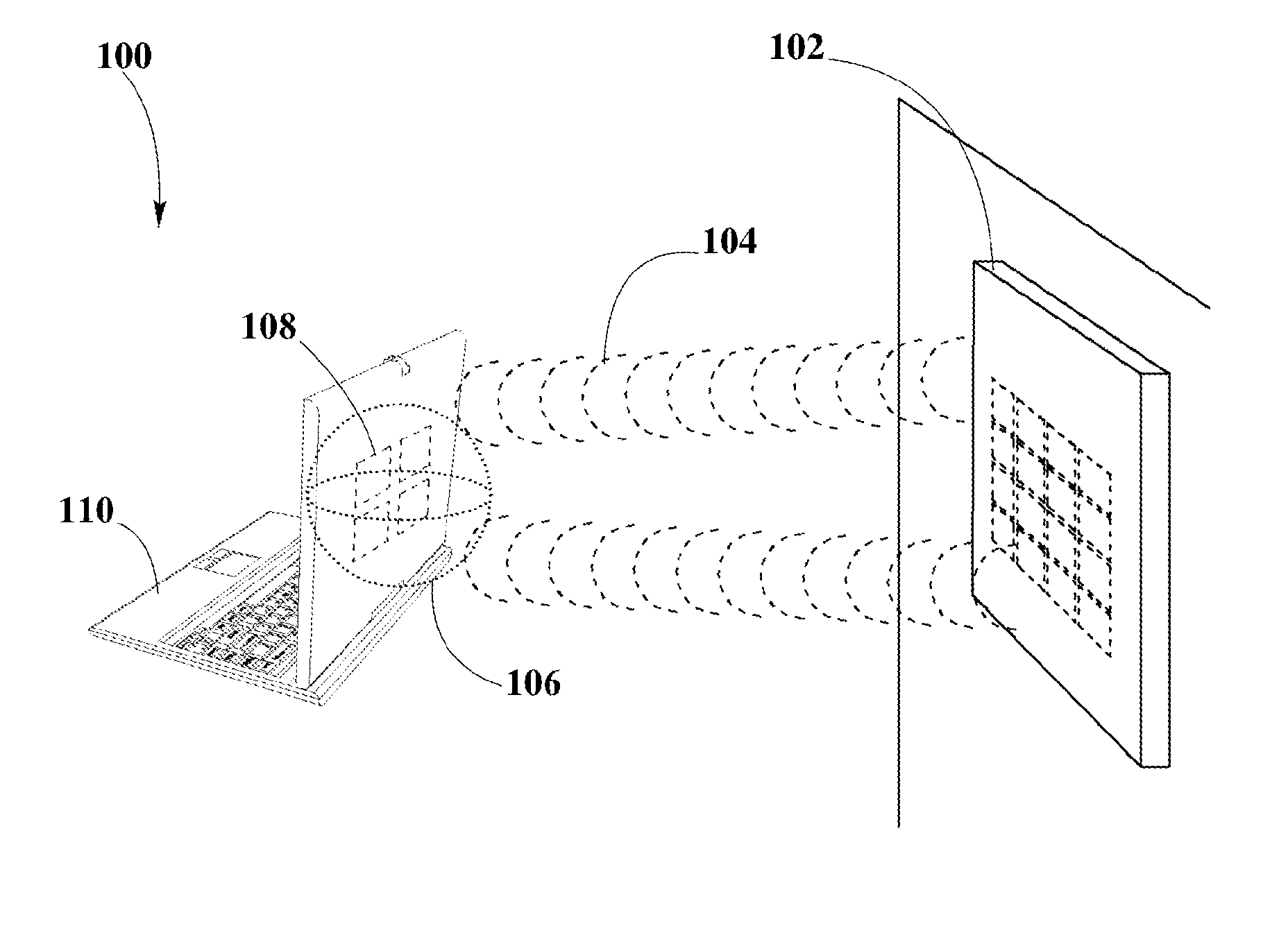
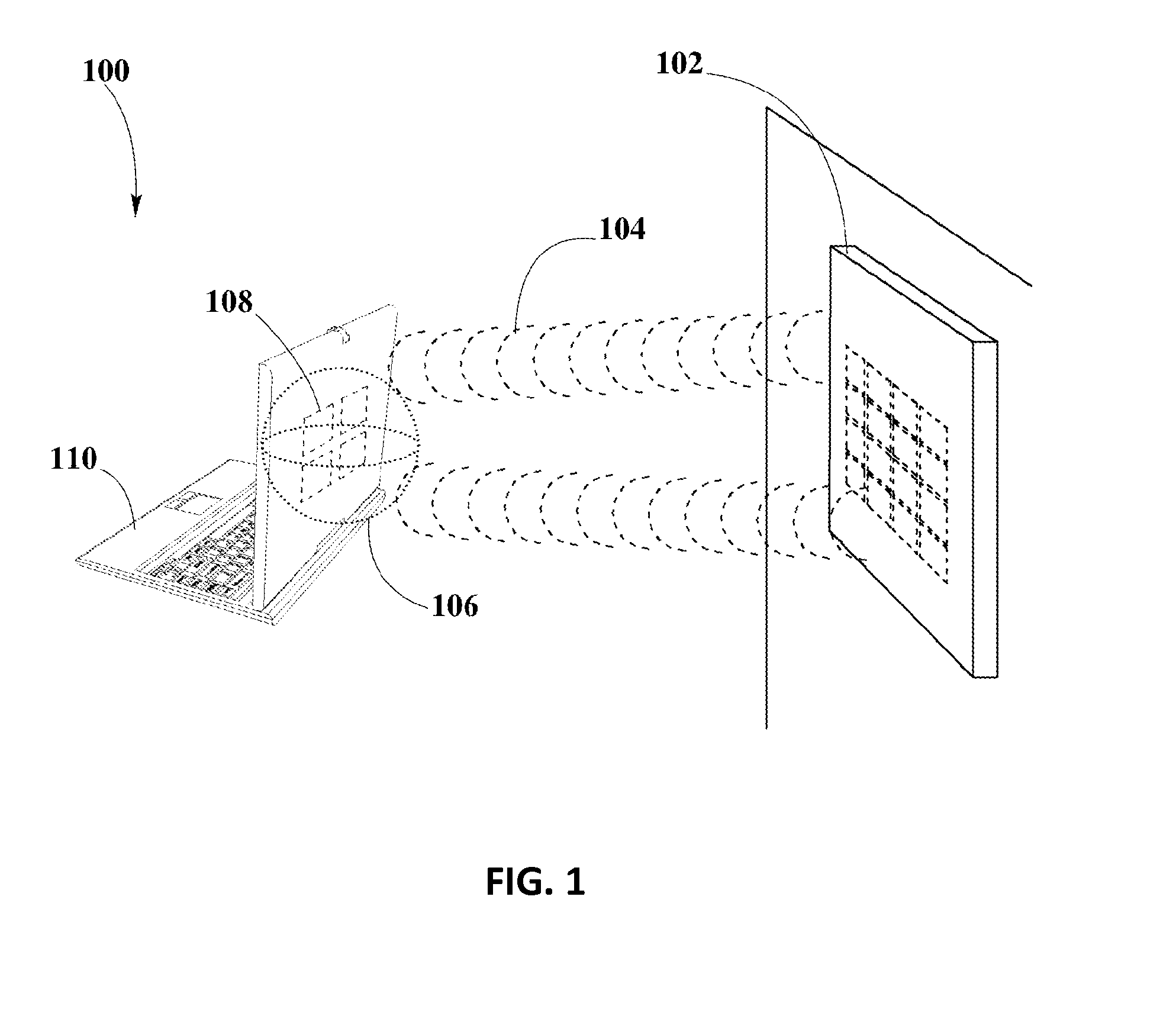
[0024]“Pocket-forming” may refer to generating two or more RF waves which converge in 3-d space, forming controlled constructive and destructive interference patterns.

[0025]“Pockets of energy” may refer to areas or regions of space where energy or power may accumulate in the form of constructive interference patterns of RF waves.

[0026]“Null-space” may refer to areas or regions of space where pockets of energy do not form because of destructive interference patterns of RF waves.

[0027]“Transmitter” may...


PUM


Abstract

A system for selecting a deselecting charging devices in a wireless power network is disclosed here. The system includes a graphical user interface from which a user may select or deselect devices to be charged in a wireless power network. The disclosed system may store records from different components of a wireless power network into a database distributed throughout said network with copies stored within the memory of wireless power transmitters.

Description

CROSS-REFERENCE TO RELATED APPLICATIONS[0001]The present disclosure is related to U.S. patent application Ser. No. 13 / 891,399 entitled Receivers For Wireless Power Transmission, filed May 10, 2013, U.S. patent application Ser. No. 13 / 891,430 entitled Methodology For Pocket-Forming, filed May 10, 2013, and U.S. patent application Ser. No. 13 / 891,445 entitled Transmitters For Wireless Power Transmission, filed May 10, 2013, each of which are incorporated by reference in their entirety herein.[0002]N / ABACKGROUND[0003]1. Field of the Disclosure[0004]The present disclosure relates in general to wireless power transmission, and more specifically to a system software for enabling a user to select and deselect devices to charge in a wireless power transmission network.[0005]2. Background Information[0006]Electronic devices such as laptop computers, smartphones, portable gaming devices, tablets and so forth may require power for performing their intended functions. This may require having to...

Claims


Application Information

Patent Timeline
Patent Type & Authority Applications(United States)
IPC IPC(8): H02J7/02
CPCH02J7/025H02J50/80H02J7/00045H02J50/402H02J50/20
Inventor BELL, DOUGLASLEABMAN, MICHAEL
Owner ENERGOUS CORPORATION
Why Eureka
Try Eureka