Dental valve tailpiece

a tailpiece and dental valve technology, applied in the field of tailpieces for dental instruments, can solve the problems of hose damage, barbs or threads associated with tailpieces can damage the hose connected to the source of vacuum, and the suggested procedure is rarely followed, etc., to achieve the effect of convenient installation, convenient handling and convenient installation

Active Publication Date: 2016-01-21
STOMA VENTURES
View PDF29 Cites 5 Cited by
  • Summary
  • Abstract
  • Description
  • Claims
  • Application Information

AI Technical Summary

Benefits of technology

[0010]The present disclosure provides a tailpiece for a dental valve device that has a proximal end that does not damage a hose being inserted on the tailpiece.
[0011]The present disclosure provides a tailpiece for a dental valve device that is easy to install on a hose connected to a source of vacuum and on to the dental valve device.
[0012]The present disclosure provides a tailpiece for a dental valve that is small, lightweight, easy to handle, and easy to install.
[0013]The present disclosure also provides a tailpiece for a dental valve which is of simple construction and design and which can be easily employed with highly reliable results.

Problems solved by technology

However, although it is suggested to sterilize the valve after use, it is known that this suggested procedure is hardly ever followed.
The barbs or threads have sharp edges and inserting or removing the hose may damage the hose.
Although these tailpieces and dental systems are beneficial, one disadvantage associated with their use is that the barbs or threads associated with the tailpieces can damage the hose connected to the source of vacuum.
Also, in a very busy dental practice, having one station out of commission for a period time may also require that several appointments will have to be canceled and rescheduled.

Method used


Image

  • Dental valve tailpiece
  • Dental valve tailpiece
  • Dental valve tailpiece

Examples


Embodiment Construction

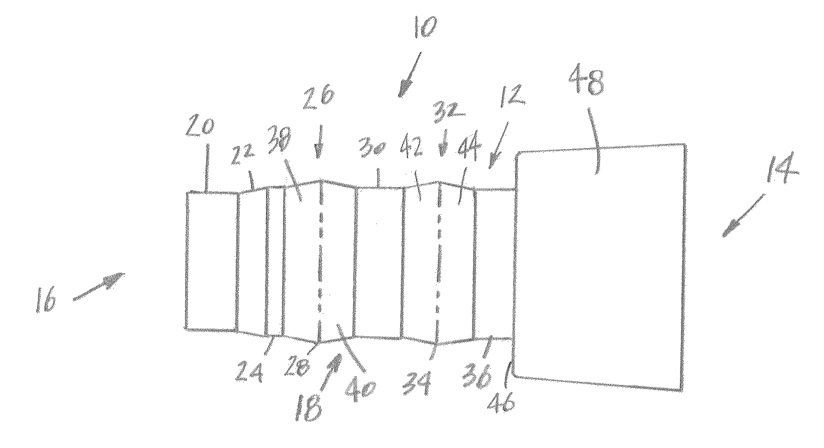
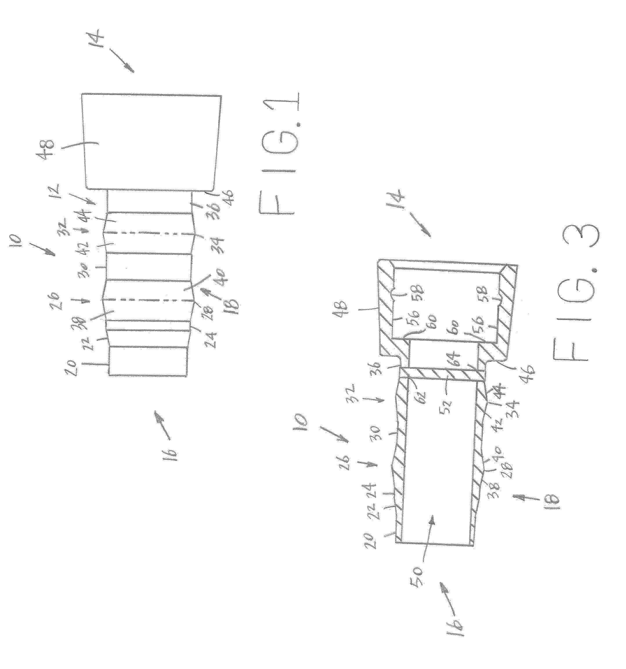
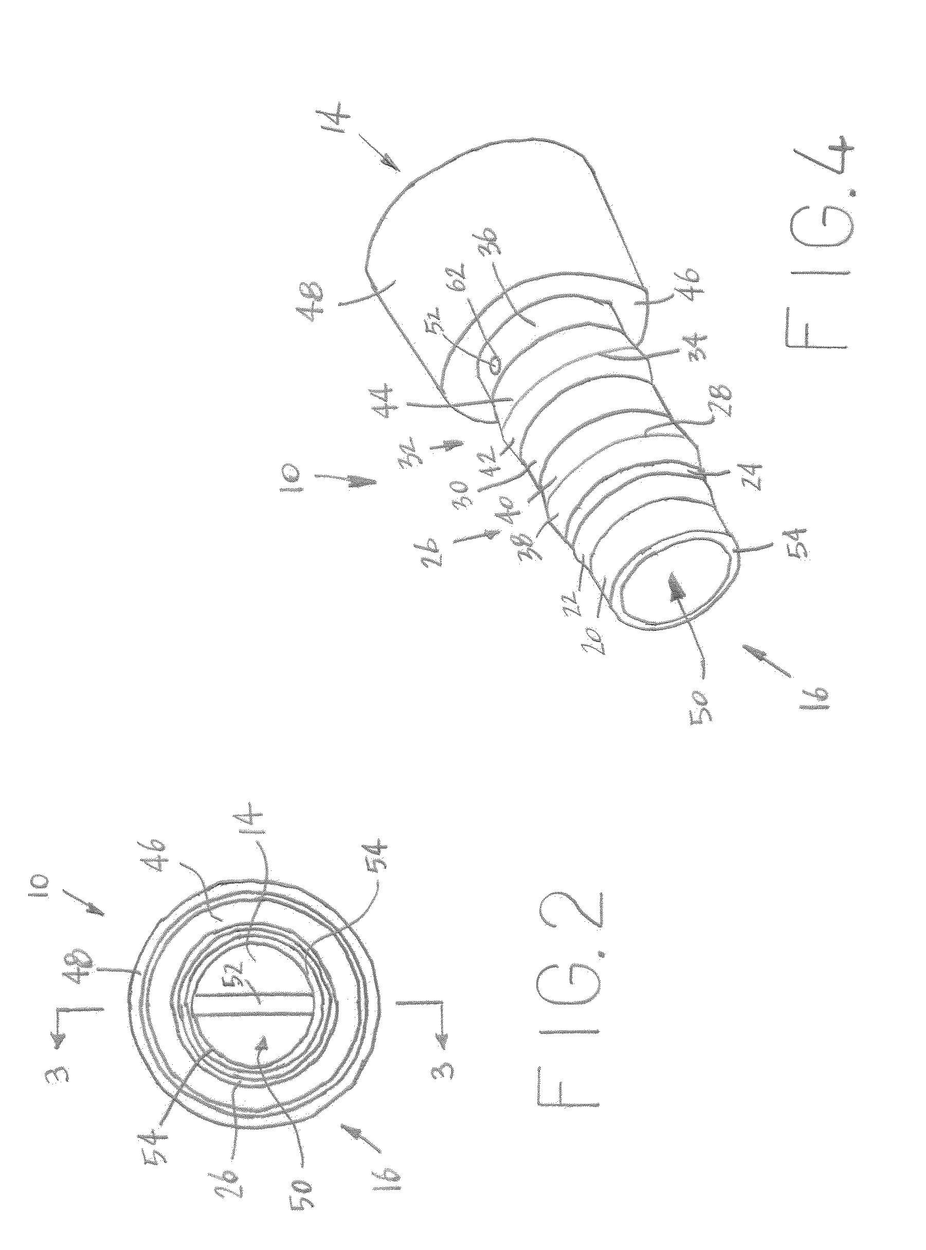
[0024]Referring now to the drawings, wherein like numbers refer to like items, number 10 identifies a tailpiece for a dental valve device for use with a dental system constructed according to the present disclosure. With reference now to FIG. 1, the tailpiece 10 comprises a body 12 having a valve receiving or distal end 14, a hose receiving or proximal end 16, and a hose retaining section 18. The valve receiving end 14 is adapted to receive a dental valve (not shown) with the valve adapted to receive an evacuator tip device (not shown) such as a high volume evacuator that is used during a dental operation or procedure. The hose receiving end 16 is adapted to receive a vacuum line or a hose (not shown) which is connected to a suction system (also not shown).

[0025]The hose retaining section 18 has a hose insertion section 20, an inclined section 22, a first flat section 24, a first tapered ring section 26 having a central section or portion 28, a second flat section 30, a second taper...


PUM


Abstract

A tailpiece for a dental valve device is disclosed which has a body having a valve receiving end, a hose receiving end, and a hose retaining section having a hose insertion section, an inclined section, a first flat section, a first tapered ring section having a central section, a second flat section, a second tapered ring section having a central section, and a third flat section.

Description

RELATED APPLICATION[0001]This application claim priority to U.S. Provisional Patent Application Ser. No. 62 / 025,593, filed on Jul. 17, 2014, the disclosure of which is incorporated herein by reference.BACKGROUND[0002]This disclosure relates to a tailpiece for a dental instrument and more particularly to a tailpiece used in conjunction with a dental valve device for a high volume evacuator or a low volume evacuator (saliva ejector).[0003]During a dental procedure it is important to be able to remove saliva, blood, tooth fragments, metals, and other debris from the mouth of a patient. Removal of this matter allows a dentist to be able to perform a procedure in an unobstructed manner. Various systems or devices have been developed to remove liquid and solid materials from a mouth during a dental procedure. One device that is capable of removing saliva is known as a saliva ejector. A saliva ejector typically comprises a plastic flexible tube or tip for placement in the mouth of a patien...

Claims


Application Information

Patent Timeline
Patent Type & Authority Applications(United States)
IPC IPC(8): A61C1/00A61C17/06
CPCA61C17/043A61C1/0061A61C17/08
Inventor ELLIS, MARKARGUELLO, EDWARD
Owner STOMA VENTURES
Why Eureka
Try Eureka