
Noise attenuating acoustic panel

a technology of acoustic panels and noise attenuation, which is applied in the field of acoustic panels to attenuate noise, can solve the problems of increasing the thickness of the honeycomb core and the thickness of the acoustic sandwich panel

Active Publication Date: 2016-01-21
RTX CORP
View PDF9 Cites 12 Cited by
  • Summary
  • Abstract
  • Description
  • Claims
  • Application Information

AI Technical Summary

Benefits of technology

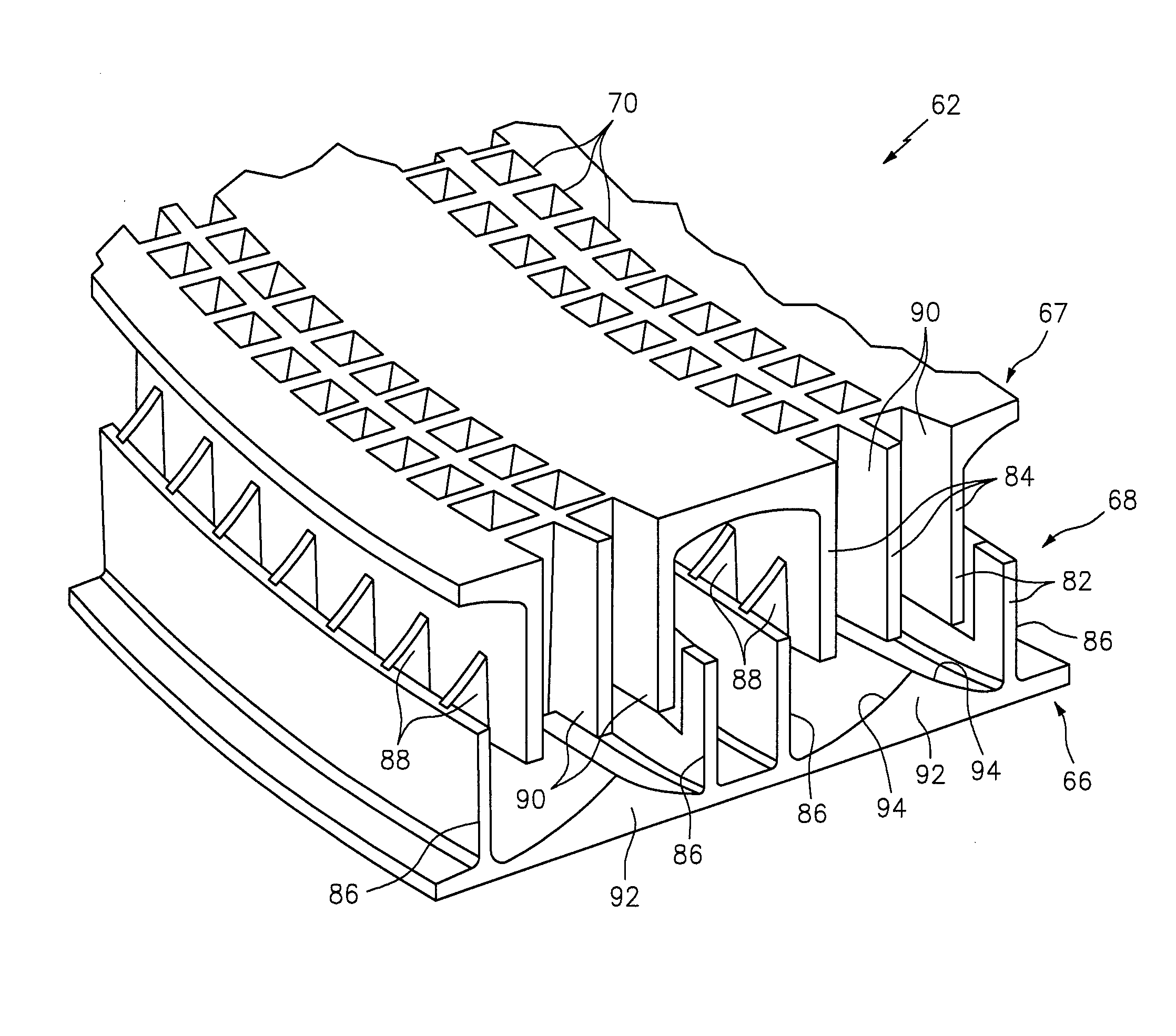
The invention relates to an acoustic panel that includes a first layer, a perforated second layer, a core and a noise attenuating feature. The noise attenuating feature is partially integrated with one or more layers of the acoustic panel and partially projects into an internal chamber of the panel. This feature can be formed using an additive manufacturing system. The acoustic panel can be used in a variety of applications such as a turbine engine, and can help reduce noise levels during operation. The noise attenuating feature can take the form of a baffle or a muffler, and may be located throughout the panel or in specific chambers. The acoustic panel is designed to offer improved noise reduction with reduced surface roughness. In some embodiments, the acoustic panel may also have one or more internal canted surfaces to further enhance its noise attenuating capabilities.

Problems solved by technology

As a result, noise energy reflected by the acoustic sandwich panel interacts with noise energy traveling towards the panel.
Differences in phase between the noise energy in an acoustic field adjacent the perforated face sheet may enable the reflected noise energy to destructively interfere with and attenuate the noise energy traveling towards the acoustic sandwich panel.
Attenuating low frequencies, however, may increase the thickness of the honeycomb core and, thus, the thickness of the acoustic sandwich panel.

Method used


Image

  • Noise attenuating acoustic panel
  • Noise attenuating acoustic panel
  • Noise attenuating acoustic panel

Examples


Embodiment Construction

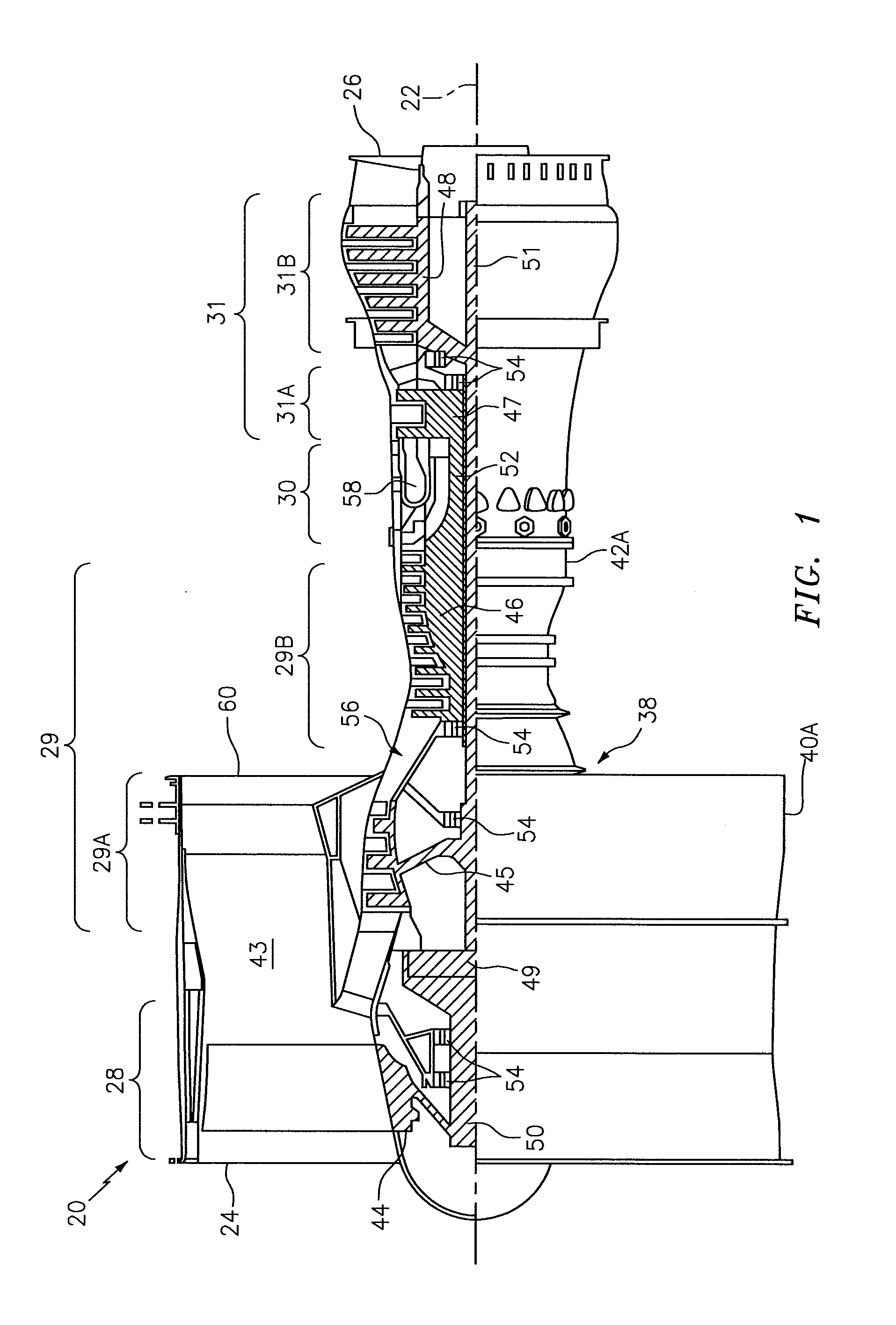
[0045]FIG. 1 is a side cutaway illustration of a geared turbine engine 20; e.g., a geared turbofan engine. This turbine engine 20 extends along an axial centerline 22 between an upstream airflow inlet 24 and a downstream airflow exhaust26. The turbine engine 20 includes a fan section 28, a compressor section 29, a combustor section 30 and a turbine section 31. The compressor section 29 includes a low pressure compressor (LPC) section 29A and a high pressure compressor (HPC) section 29B. The turbine section 31 includes a high pressure turbine (HPT) section 31A and a low pressure turbine (LPT) section 31B.

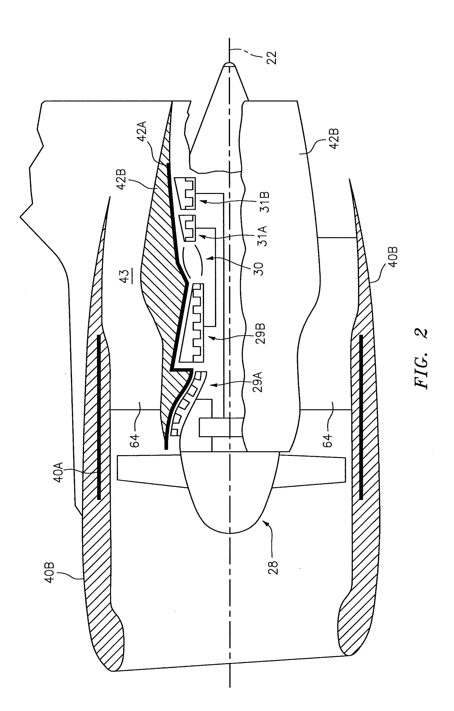
[0046]The engine sections 28-31 are arranged sequentially along the centerline 22 within an engine housing 38. This housing 38 includes an outer case 40A (e.g., a fan case) and an inner case 42A (e.g., a core case). The inner case 42A may house one or more of the engine sections 29-31; e.g., an engine core. The outer case 40A may house at least the fan section 28. Referring to FIG. 2...


PUM


Abstract

An acoustic panel is provided that includes a first layer, a perforated second layer, a core and a noise attenuating feature. The core forms a chamber between the first and the second layers. The noise attenuating feature projects partially into the chamber. The noise attenuating feature is formed integral with the first layer, the second layer and / or the core.

Description

[0001]This application claims priority to U.S. Patent Appln. No. 62 / 026,932 filed Jul. 21, 2014.BACKGROUND OF THE INVENTION[0002]1. Technical Field[0003]This disclosure relates generally to an acoustic panel and, more particularly, to an acoustic panel for attenuating noise generated during, for example, operation of a turbine engine.[0004]2. Background Information[0005]A gas turbine engine may include an acoustic sandwich panel for attenuating noise generated during turbine engine operation. A typical acoustic sandwich panel includes a honeycomb core bonded between a solid face sheet and a perforated face sheet. The honeycomb core includes a plurality of resonating cavities. The honeycomb core has a thickness sized to tune the resonating cavities to a specific target frequency of noise to be attenuated. As a result, noise energy reflected by the acoustic sandwich panel interacts with noise energy traveling towards the panel. Differences in phase between the noise energy in an acous...

Claims


Application Information

Patent Timeline
Patent Type & Authority Applications(United States)
IPC IPC(8): F01N1/08
CPCF01N1/082F02K1/827F02C7/045F05D2260/962F05D2260/963F05D2250/63
Inventor MATTIA, STEPHEN, H.
Owner RTX CORP
Learn More