Flat heat pipe

a heat pipe and flat technology, applied in the field of flat heat pipes, can solve the problems of difficult to ensure the vapor passage is sufficiently strong, the heating site is dried out, and the difficulty of phase changeable working fluid to be circulated, so as to reduce the thermal resistance to transport heat, improve the hydrophilicity of the inner face of the container in the evaporating portion, and spread the working fluid over the inner face smoothly.

Inactive Publication Date: 2016-01-21
THE FUJIKURA CABLE WORKS LTD
View PDF12 Cites 9 Cited by
  • Summary
  • Abstract
  • Description
  • Claims
  • Application Information

AI Technical Summary

Benefits of technology

[0019]Thus, in the flat heat pipe of the present invention, the groove wick is formed on the inner face of the container in the evaporating portion. According to the present invention, therefore, hydrophilicity on the inner face of the container in the evaporating portion can be improved to spread the working fluid over the inne

Problems solved by technology

However, since an inner volume of the thin flat heat pipe is rather small, it is difficult to circulate the phase changeable working fluid.
Given that a large wick structure is arranged in the container to enhance capillary pumping to pull the working fluid to a heating site, most part of the internal space would be occupied by the wick structure, and hence it is difficult to ensure t

Method used


Image

  • Flat heat pipe
  • Flat heat pipe
  • Flat heat pipe

Examples


Embodiment Construction

)

[0029]Hereinafter, preferred examples of the flat heat pipe according to the present invention will be explained in more detail with reference to the accompanying drawings.

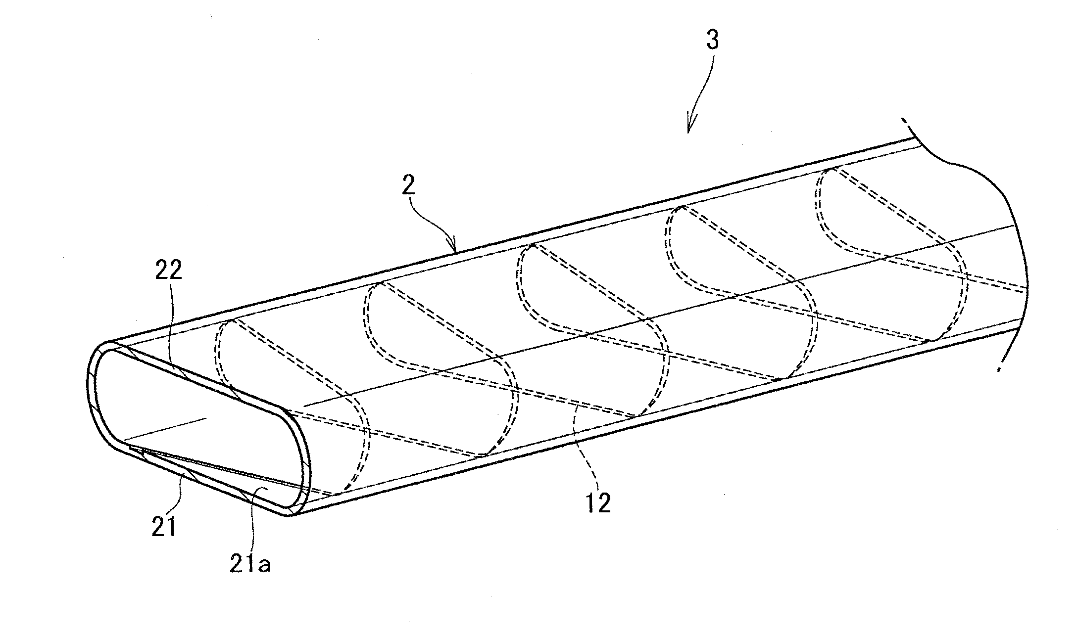
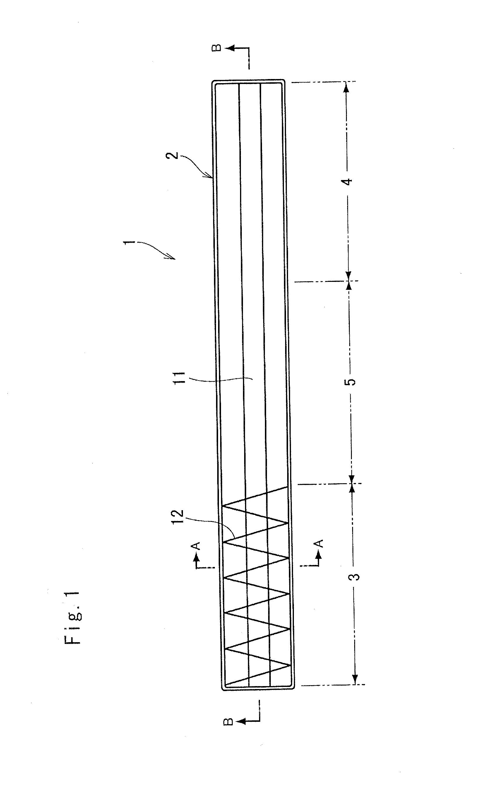
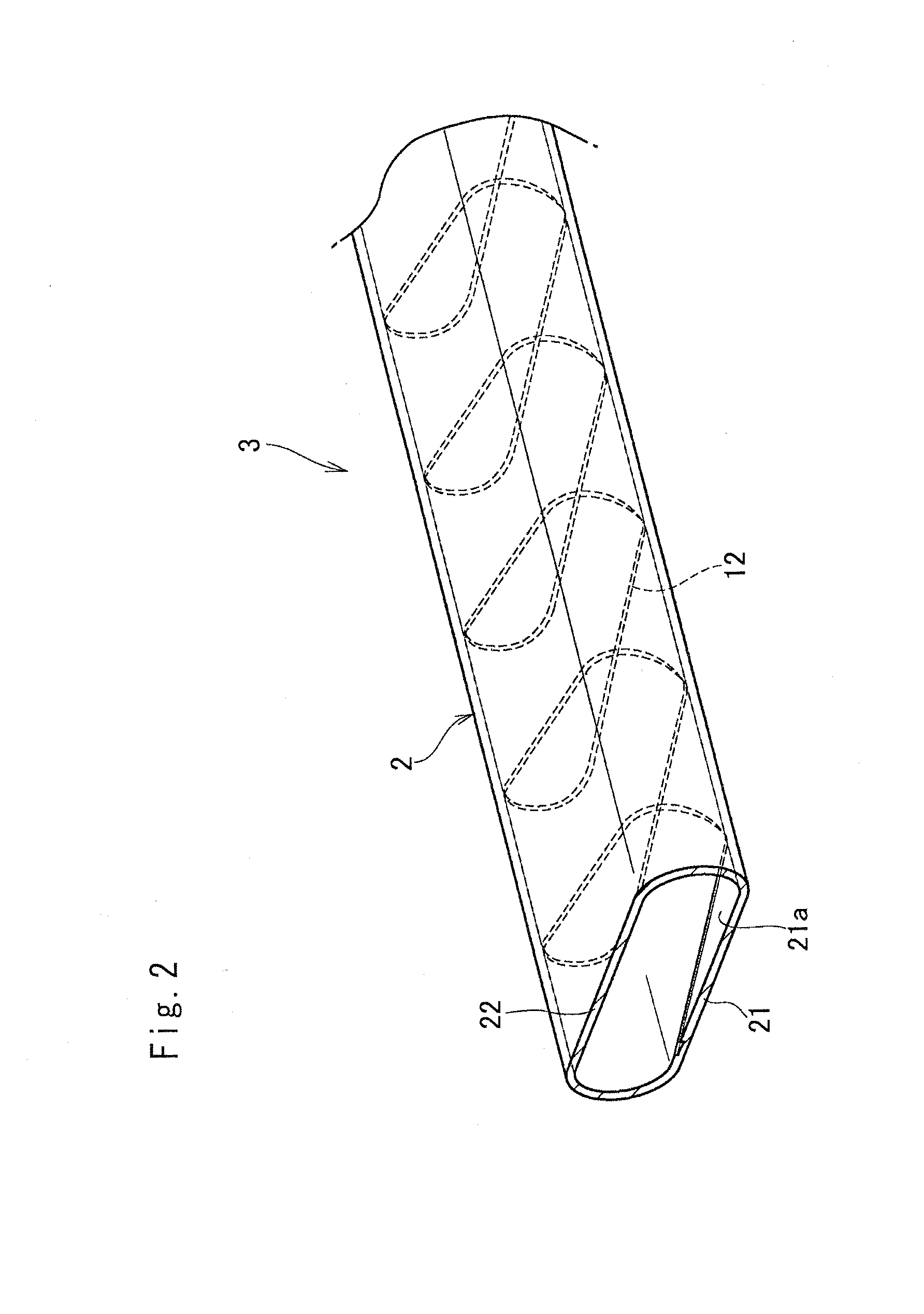
[0030]Referring now to FIG. 1, there is shown a heat pipe 1 according to the preferred example. The heat pipe 1 shown therein is a heat transport device adapted to transport heat in the form of latent heat of phase changeable working fluid encapsulated in a sealed container 2.

[0031]The container 2 is flattened to have flat longitudinal walls, and both ends are closed. In the heat pipe 1, one of the end portions serves as an evaporating portion 3 and the other end serves as a condensing portion 4, and an insulated portion 5 therebetween is insulated from an external heat.

[0032]The evaporating portion 3 is brought into contact to a heat generating element, and the working fluid held therein is heated by a heat of the heat generating element. According to the preferred example, approximately third part of the contai...


PUM


Abstract

A heat pipe a flat heat pipe having enhanced heat transport capacity is provided. The flat heat pipe 1 comprises a working fluid encapsulated in a container 2, a first wick 11 that returns the working fluid from a condensing portion 4 to an evaporating portion 3 by a capillary pumping, and a second wick 12 that spreads the working fluid returned thereto over an inner face of the container by a capillary pumping. The second wick is formed only in the evaporating portion 3 to extend in a circumferential direction on the inner face of the container2.

Description

[0001]The present invention claims the benefit of Japanese Patent Application No. 2014-146261 filed on Jul. 16, 2014 with the Japanese Patent Office, the disclosure of which is incorporated herein by reference in its entirety.BACKGROUND[0002]1. Field of the Invention[0003]The present invention relates to an art of a flat heat pipe having a wick structure.[0004]2. Discussion of the Related Art[0005]Heat pipe adapted to transport heat utilizing latent heat of fluid has been widely used as a heat transport device. The conventional heat pipe comprises a tubular sealed container and working fluid encapsulated therein, and both ends of the container are closed. The working fluid is vaporized by a heat of the heat generating element transmitted to one end of the heat pipe, and flows toward the other end to be cooled.[0006]In general, one of the end portions of the heat pipe is brought into contact to the heat generating element to evaporate the working fluid, and the other end portion is b...

Claims


Application Information

Patent Timeline
IPC IPC(8): F28D15/04
CPCF28D15/04F28D15/0233F28D15/046
Inventor AHAMED, MOHAMMAD SHAHEDSAITO, YUJI
Owner THE FUJIKURA CABLE WORKS LTD
Why Eureka
Try Eureka