Medical tested object auto-ejection structure and blood-gas analyzer using same

a technology of auto-ejection structure and medical equipment, which is applied in the direction of mechanical equipment, machines/engines, instruments, etc., can solve the problems of prior art defects, contaminated instruments, and residuals in the tested object to flow out and contaminate instruments, so as to improve the reliability of the product

Active Publication Date: 2016-01-21
EDAN INSTR
View PDF0 Cites 5 Cited by
  • Summary
  • Abstract
  • Description
  • Claims
  • Application Information

AI Technical Summary

Benefits of technology

[0016]According to the technical solution provided by the invention, an insertion port is formed in the detection instrument. When the tested object is inserted in the instrument through the insertion port, the bottom end of the tested object presses a bulge used for rebounding, and a raised step arranged on the surface of one side of the tested object is locked on a clamping buckle arranged at a position corresponding to the step on the instrument simultaneously. After a test is finished, the instrument releases the locking of the clamping buckle for the tested object by a transmission device, and the tested object is ejected from the instrument in time under the action of the bulge used for rebounding, thus solving the problem of forgetting to pull out the tested object or not being able to pull it out in time, and improving the reliability of the product.

Problems solved by technology

If the tested object is pulled out too early, the instrument may be damaged and hence the correct measurements cannot be obtained, if the tested object is pulled out late, the control for the tested object may be stopped as the instrument completes the test, causing the residue in the tested object to flow out and contaminate the instrument, etc.
If the staff is not nearby, this will result in the risk that the tested object is not pulled out in time and hence causes the tested object to contaminate the instrument.
Therefore, the prior art has a defect.

Method used


Image

  • Medical tested object auto-ejection structure and blood-gas analyzer using same
  • Medical tested object auto-ejection structure and blood-gas analyzer using same
  • Medical tested object auto-ejection structure and blood-gas analyzer using same

Examples


Embodiment Construction

[0028]The invention will be further described in more details and the object, the technical solution and the advantages of the invention will be more apparent with the combination of the following drawings and embodiments. It shall be understood that the embodiments described herein are only used for explaining the invention but do not limit the invention.

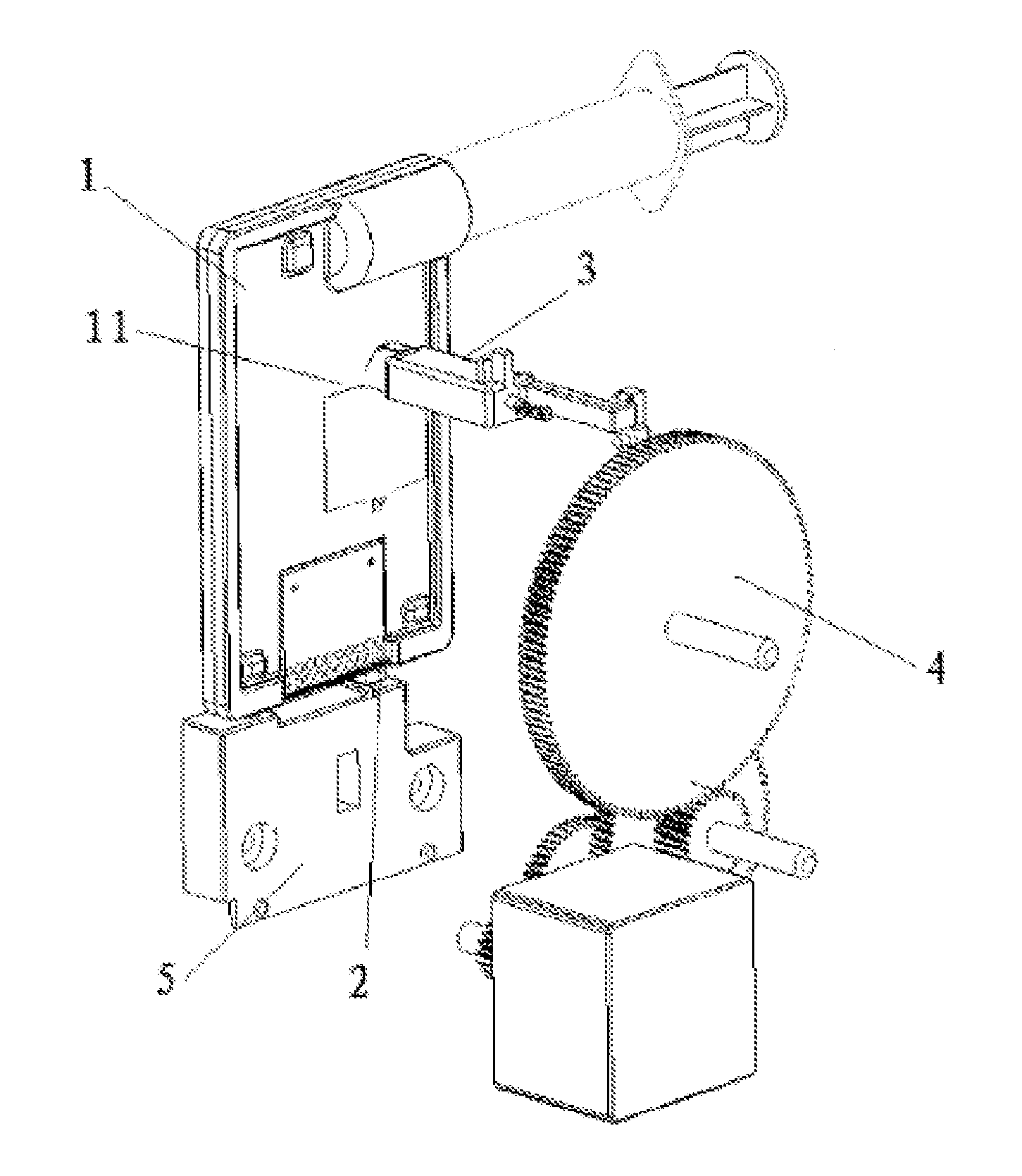
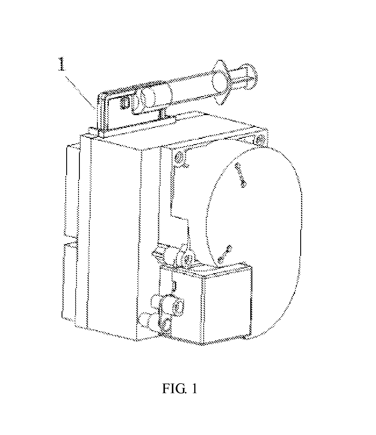
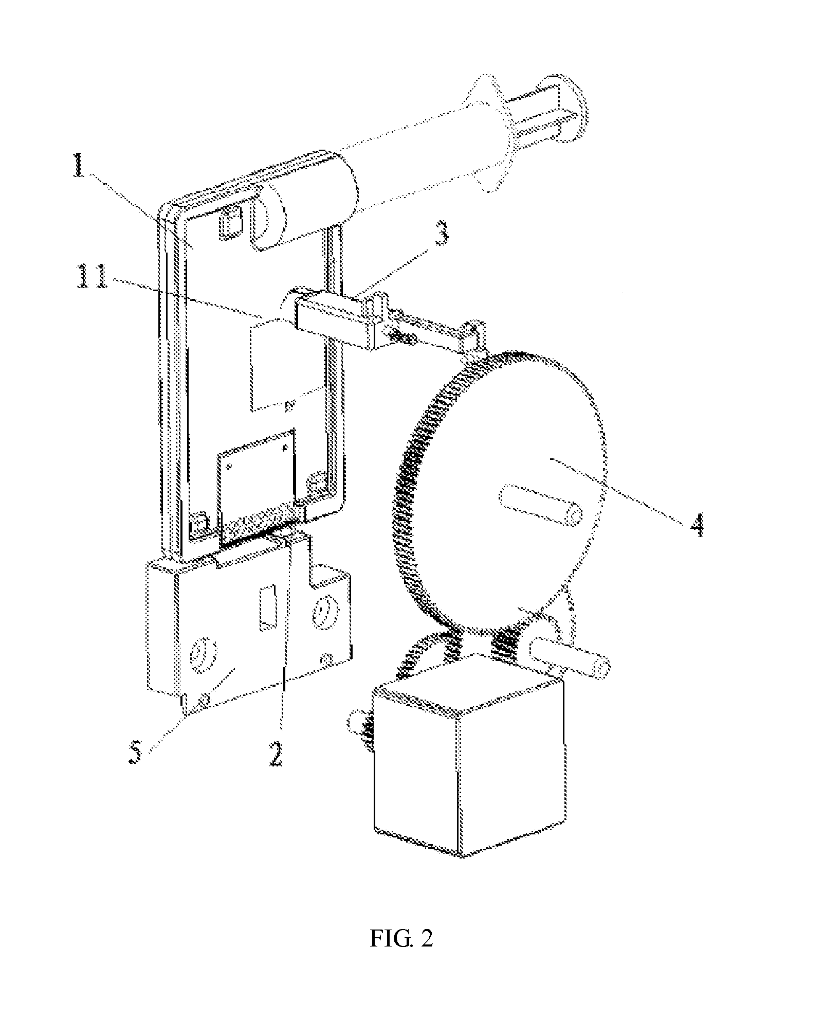
[0029]As shown in FIGS. 1, 2, the invention has the following technical solution to solve the technical problems:

[0030]An insertion port is formed in the detection instrument, a tested object (for example, a technical solution of a test card, a test bottle or a test pipe which is loaded with a test liquid, preferably the test card, is described) is inserted into the instrument through the insertion port, a raised step 11 is arranged on the surface of one side of the test card 1, a rebounding device 2 and a clamping buckle device 3 arranged in the detection instrument are respectively assembled on a base 5 right under which the test...


PUM

PropertyMeasurementUnit
auto-ejection structureaaaaaaaaaa
heightaaaaaaaaaa
shapeaaaaaaaaaa

Abstract

A medical tested object auto-ejection structure comprises a detection instrument and a tested object (1). An insertion port is formed in the detection instrument. When the tested object (1) is inserted in the instrument through the insertion port, the bottom end of the tested object (1) presses a bulge (21) used for rebounding, and a raised step (11) arranged on the surface of one side of the tested object (1) is locked on a clamping buckle (31) arranged at a position corresponding to the step on the instrument simultaneously, and after a test is finished, the instrument releases the locking of the clamping buckle (31) for the tested object (1) by a transmission device, and the tested object (1) is ejected from the instrument in time under the action of the bulge (21) used for rebounding, thus solving the problem of forgetting to pull the tested object out or inability to pull it out in time, and improving the reliability of the product.

Description

FIELD OF THE INVENTION[0001]The invention relates to the field of a mechanical ejection structure of medical equipment, and specifically to a medical tested object auto-ejection structure.BACKGROUND OF THE INVENTION[0002]In the medical field, when a sample is tested, a tested object (for example, blood, a tested card used in blood gas analysis equipment) is inserted into a test instrument for testing and analysis. This form of testing is widely used in medical equipment. When the test is completed, the prompt that the tested object should be pulled out is very important. If the tested object is pulled out too early, the instrument may be damaged and hence the correct measurements cannot be obtained, if the tested object is pulled out late, the control for the tested object may be stopped as the instrument completes the test, causing the residue in the tested object to flow out and contaminate the instrument, etc. Currently, on the market, an electronic lighting display form is gener...

Claims


Application Information

Patent Timeline
Patent Type & Authority Applications(United States)
IPC IPC(8): G01N35/00B01L9/00G01N33/49
CPCG01N35/00584B01L9/50G01N33/4925B01L9/00G01N33/4875Y10T436/115831G01N2035/00277G01N2035/00108B01L9/52G01N21/8483F16K1/24B01L2200/04B01L2300/0825G01N35/00712G01N35/00693F01L2305/00
Inventor HUANG, GAOXIANGZHAO, ZHIXIANG
Owner EDAN INSTR
Why Eureka
Try Eureka