Super junction semiconductor device

Active Publication Date: 2016-01-21
MAGNACHIP SEMICONDUCTOR LTD
View PDF2 Cites 9 Cited by
  • Summary
  • Abstract
  • Description
  • Claims
  • Application Information

AI Technical Summary

Benefits of technology

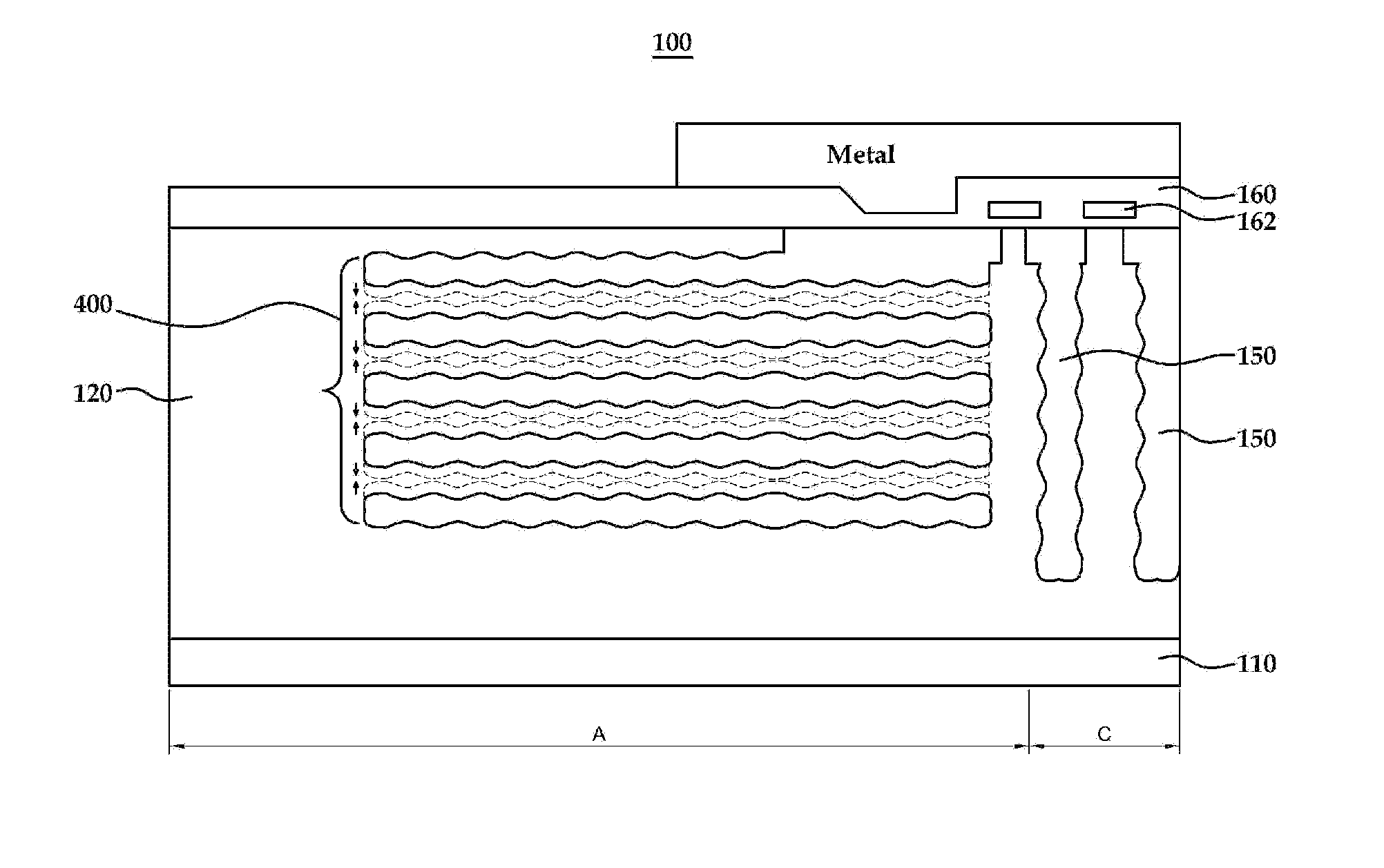
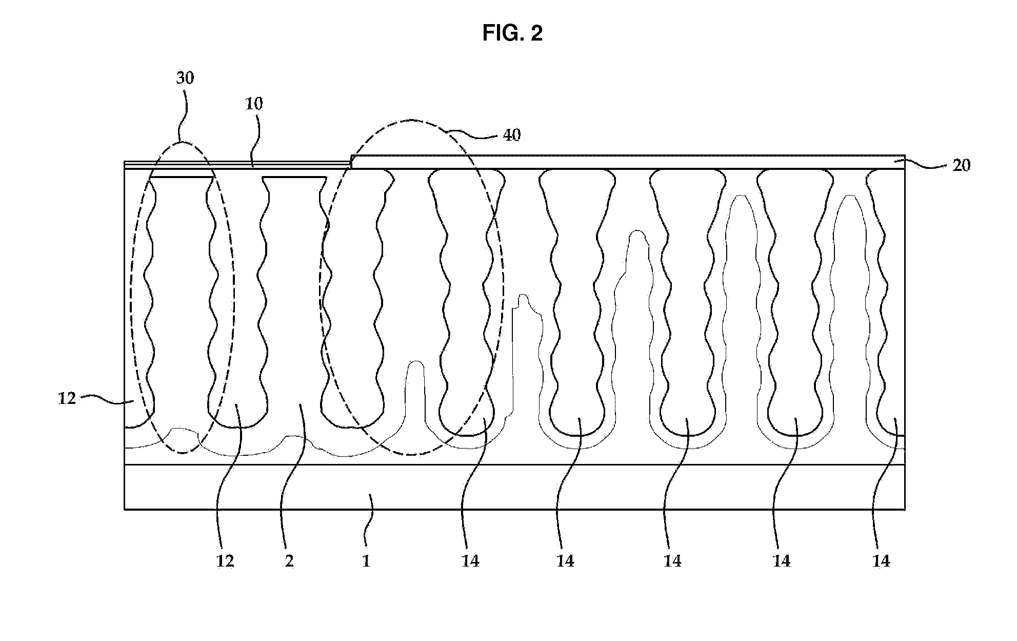
[0039]The examples enable all pillar regions on a chip to be connected with each other by forming all pillar regions of a termination region in a semiconductor device without a floating section. Thus, all N-type horizontal epi regions are located in a depleted region and are able to offset a charge-compensation difference of pillar regions that is generated reciprocally. Thus, although a termination region length

Problems solved by technology

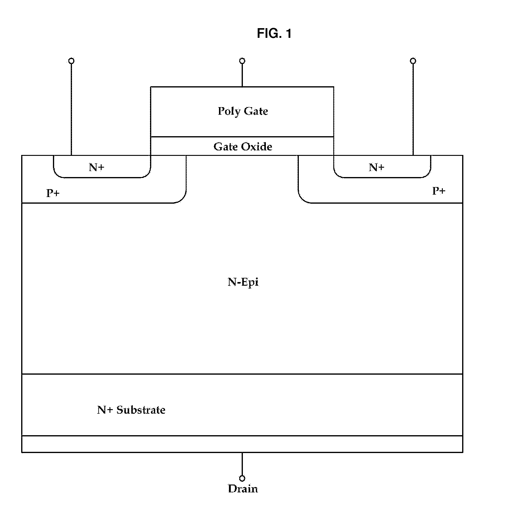
However, it is difficult to have a component below a certain resistance because of the relationships with the electric field distribution.
Especially in the case of a 500 V level MOSFET, such a device has a problem of on-resistance growing larger as a breakdown voltage increases because almost 90% of an on-resistance component is epi resistance.
Although measu

Method used


Image

  • Super junction semiconductor device
  • Super junction semiconductor device
  • Super junction semiconductor device

Examples


Embodiment Construction

[0049]The following detailed description is provided to assist the reader in gaining a comprehensive understanding of the methods, apparatuses, and / or systems described herein. However, various changes, modifications, and equivalents of the methods, apparatuses, and / or systems described herein will be apparent to one of ordinary skill in the art. The sequences of operations described herein are merely examples, and are not limited to those set forth herein, but may be changed as will be apparent to one of ordinary skill in the art, with the exception of operations necessarily occurring in a certain order. Also, descriptions of functions and constructions that are well known to one of ordinary skill in the art may be omitted for increased clarity and conciseness.

[0050]The features described herein may be embodied in different forms, and are not to be construed as being limited to the examples described herein. Rather, the examples described herein have been provided so that this disc...


PUM


Abstract

Provided is a super junction semiconductor device. The super junction semiconductor device includes a vertical pillar region located in an active region and horizontal pillar regions located in a termination region that are connected with each other while simultaneously not floating the entire pillar region in the termination region. Thus, a charge compensation difference, generated among pillar regions, is caused to be offset, although the length of the termination region is relatively short.

Description

CROSS-REFERENCE TO RELATED APPLICATION(S)[0001]This application claims the benefit under 35 USC 119(a) of Korean Patent Application No. 10-2014-0091152 filed on Jul. 18, 2014, in the Korean Intellectual Property Office, the entire disclosure of which is incorporated herein by reference for all purposes.BACKGROUND[0002]1. Field[0003]The following description relates to a semiconductor device. The following description also relates to a super junction semiconductor device, including one cell as a whole by connecting with each other a pillar region of an active region and a pillar region formed in a termination region that surrounds the active region without floating.[0004]2. Description of Related Art[0005]In alternatives, a high voltage device and a high power device are used in a power IC device for electric power conversion and in an electric control system. For example, a planar gate type MOSFET is used frequently as an IC device.[0006]A cross sectional diagram of a unit cell of a...

Claims


Application Information

Patent Timeline
IPC IPC(8): H01L29/06H01L29/78
CPCH01L29/7811H01L29/0634H01L29/0615H01L29/78H01L29/7842
Inventor WOO, HYUKKIM, DAE BYUNGCHOI, CHANG YONGKANG, KI TAEJUN, KWANG YEONCHO, MOON SOOKWON, SOON TAK
Owner MAGNACHIP SEMICONDUCTOR LTD
Why Eureka
Try Eureka