Planar horn array antenna
a technology of horn array and antenna, which is applied in the direction of antennas, linear waveguide fed arrays, waveguide horns, etc., can solve the problems of increasing the rental fee of the communication satellite, reducing the transmission speed of the signal from the planar horn array antenna, and affecting the reception of the signal between adjacent communication satellites, so as to minimize the occurrence of grating lobes
Active Publication Date: 2016-01-21
WIWORLD
View PDF8 Cites 17 Cited by
- Summary
- Abstract
- Description
- Claims
- Application Information
AI Technical Summary
Benefits of technology
The patent text describes a planar horn array antenna that reduces the occurrence of grating lobe. The antenna includes a waveguide part, a horn part, and a radio wave guide part. The radio wave guide part has a dividing member consisting of circular dividing holes arranged in a matrix of n×n, which divides the radio wave into n radio waves. The antenna also includes polarizer members that control the angle of the radio waves incident or emitted to the dividing holes, allowing for control of the skew angle without mechanically rotating. The technical effect is improved performance and minimized interference between radio waves.
Problems solved by technology
However, a plurality of communication satellites are densely arranged above the equator now, and therefore signal interference occurs between adjacent communication satellites even when the signals from the planar horn array antenna are transmitted to the preset communication satellites.
However, the method has a problem in that a transmission speed of the signal from the planar horn array antenna may be reduced and a rental fee of the communication satellite may be increased.
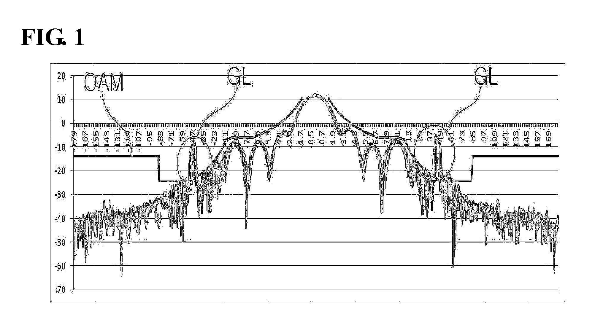
When the array interval of the elements is equal to or more than λ / 2, there is a problem in that a grating lobe (GL) occurs.
To solve the above problems, Korean Patent Laid-Open Publication No. 2008-0105856 discloses a dual linear polarization horn array antenna, which may reduce a size of the antenna but may not solve the grating lobe occurring from the planar horn array antenna.
However, for the planar horn array antenna to control the skew angle, the planar horn array antenna needs to mechanically rotate, which leads to a problem in that the planar horn array antenna is complicated, takes up much space, and has reduced accuracy.
Method used
View moreImage
Smart ImageViewing Examples

Examples
Embodiment Construction
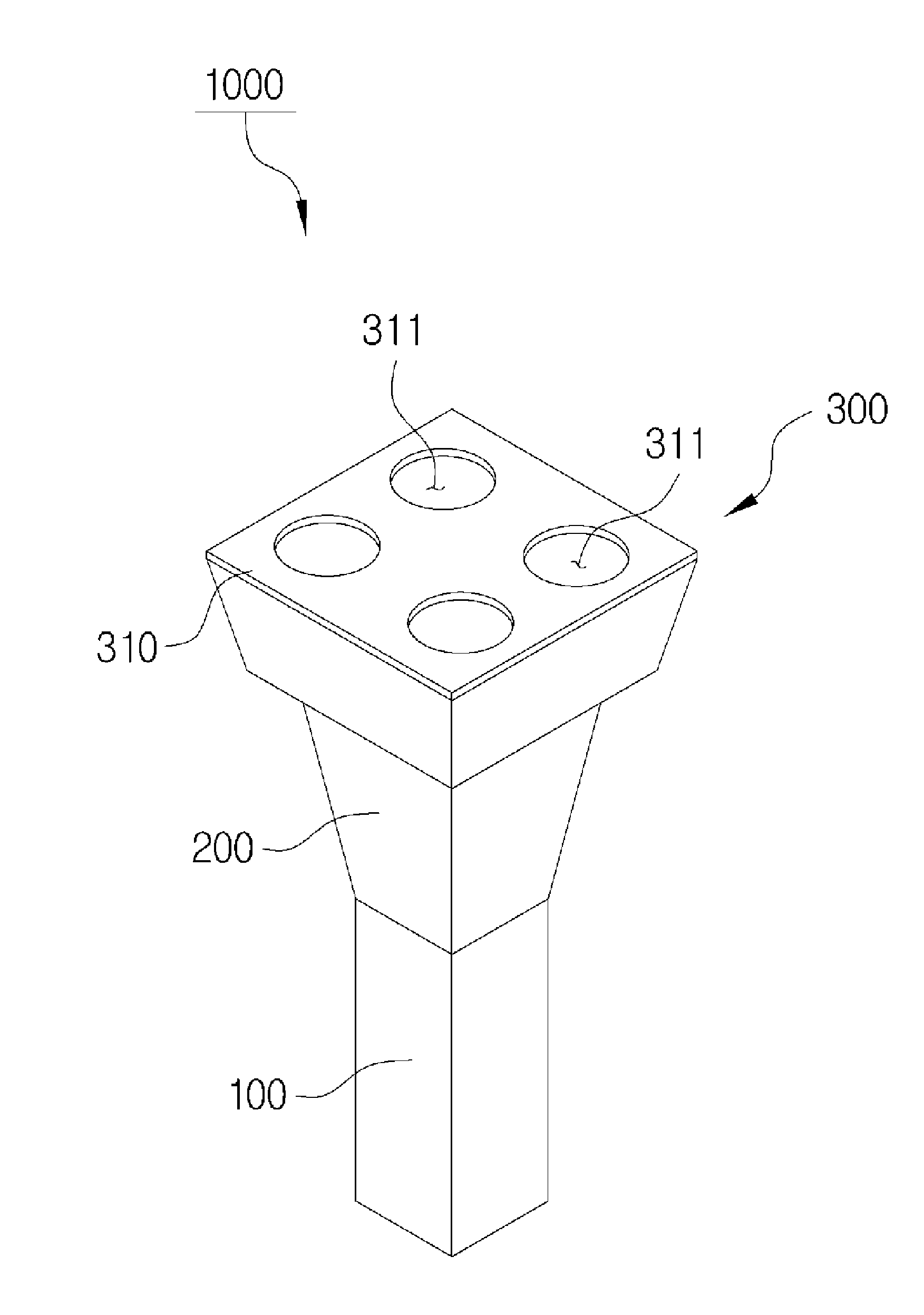
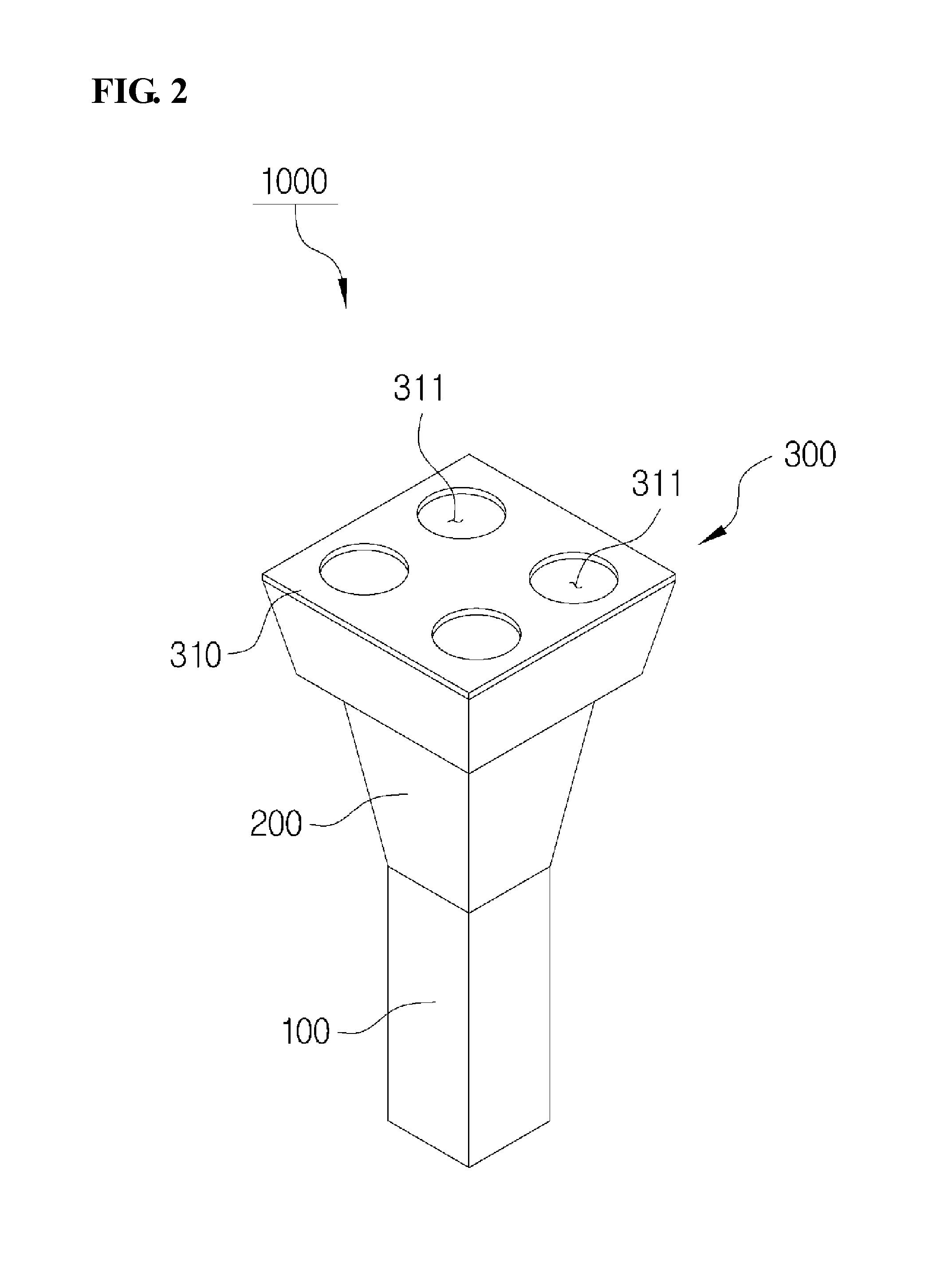
[0072]1000: Planar horn array antenna according to the invention
[0073]100: Waveguide part
[0074]200: Horn part
[0075]201, 201′: Opening
[0076]300, 300′, 300″: Radio wave guide part
[0077]310: Dividing member
[0078]311: Dividing hole
[0079]320: Cover member
[0080]330, 330′, 330″: Polarizer member
Login to View More PUM
 Abstract
Provided is a planar horn array antenna includes: a waveguide part; a horn part having one side connected to the waveguide part and the other side formed with an opening for guiding a radio wave incident or emitted thereto; and a radio wave guide part having a dividing member coupled with the opening and consisting of circular dividing holes arranged in a matrix of n×n.
Description
TECHNICAL FIELD[0001]The present invention relates to a planar horn array antenna.BACKGROUND ART[0002]Generally, an antenna is to radiate a radio wave to a free space or receive the radio wave. The antenna may be generally classified into a linear antenna, an aperture antenna, a micro strip antenna, a planar horn array antenna, a reflector antenna, a lens antenna, etc., based on various classification standards.[0003]The radio wave radiated from the antenna has a predetermined pattern. Here, a polarization of the radiated radio wave is classified into a linear polarization, a circular polarization, an elliptical polarization, etc., depending on a direction in which an electric field or a magnetic field vibrates and a direction in which a wave proceeds.[0004]In this case, the circular polarization among the polarizations of the radio wave radiated from the antenna is a radio wave in which a locus of a vector end representing a magnitude and a direction of the electric field draws a c...
Claims
Login to View More Application Information
Patent Timeline
 Patent Type & Authority Applications(United States)
IPC IPC(8): H01Q13/02H01Q15/24H01Q21/00
CPCH01Q13/02H01Q21/0037H01Q15/24H01Q19/08H01Q21/06
Inventor PARK, CHAN GOOLEE, JUN HEE
Owner WIWORLD
Features
- Generate Ideas
- Intellectual Property
- Life Sciences
- Materials
- Tech Scout
- Unparalleled Data Quality
- Higher Quality Content
- 60% Fewer Hallucinations
Learn More Browse by: Latest US Patents, China's latest patents, Technical Efficacy Thesaurus, Application Domain, Technology Topic, Popular Technical Reports.
© 2025 PatSnap. All rights reserved.Legal|Privacy policy|Modern Slavery Act Transparency Statement|Sitemap|About US| Contact US: help@patsnap.com