
Flow detection system for flow control apparatus

a detection system and flow control technology, applied in the direction of intravenous devices, other medical devices, drugs and medications, etc., can solve the problems of damage to the feeding set and the flow control apparatus, and it is difficult for the system to distinguish between abnormal and normal flow conditions, so as to relieve the deformation of the feeding set, relieve the deformation, and relieve the effect of any built-up pressure in the feeding s

Active Publication Date: 2016-01-28
KPR U S LLC
View PDF4 Cites 3 Cited by
  • Summary
  • Abstract
  • Description
  • Claims
  • Application Information

AI Technical Summary

Benefits of technology

The patent describes a flow control apparatus for loading a feeding set for delivering fluid to a patient. The apparatus includes a housing, a pumping device, and a sensor. The sensor produces a signal indicative of pressure in the feeding set when it is loaded on the apparatus. The control circuit receives the sensor signal and operates the pumping device in an operational state to produce a peristaltic pumping action of fluid in the patient direction. The control circuit can also operate the pumping device in a hold state where it does not produce a peristaltic pumping action but relieves backflow pressure. The control circuit can also compare the sensor signal with a baseline sensor signal to determine if there is an occlusion in the feeding set. The technical effect of this invention is to provide a flow control apparatus that can effectively control the flow of fluid in the feeding set and relieve backflow pressure while also being able to detect and address any occlusions in the feeding set.

Problems solved by technology

The presence of an occlusion prevents nutritional liquid from being delivered to the patient and can damage the feeding set and flow control apparatus.
However, it can difficult for the system to distinguish between abnormal and normal flow conditions in the feeding set while the apparatus is operating to deliver fluid through the feeding set.

Method used


Image

  • Flow detection system for flow control apparatus
  • Flow detection system for flow control apparatus
  • Flow detection system for flow control apparatus

Examples


Embodiment Construction

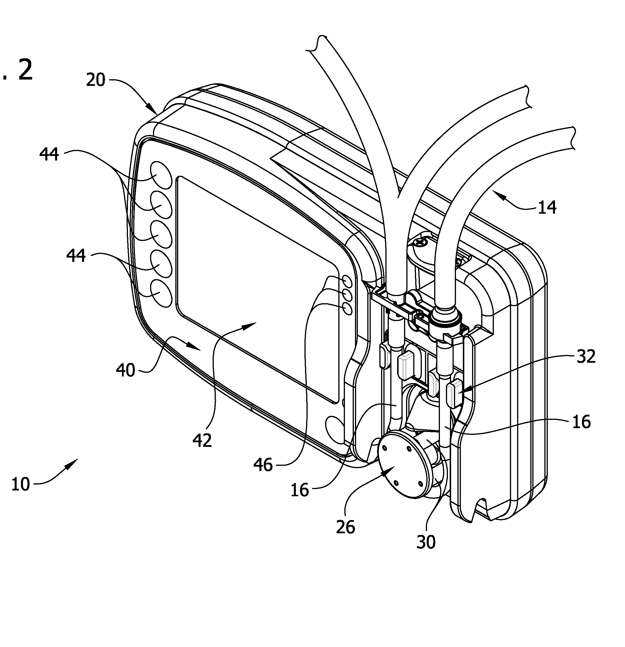
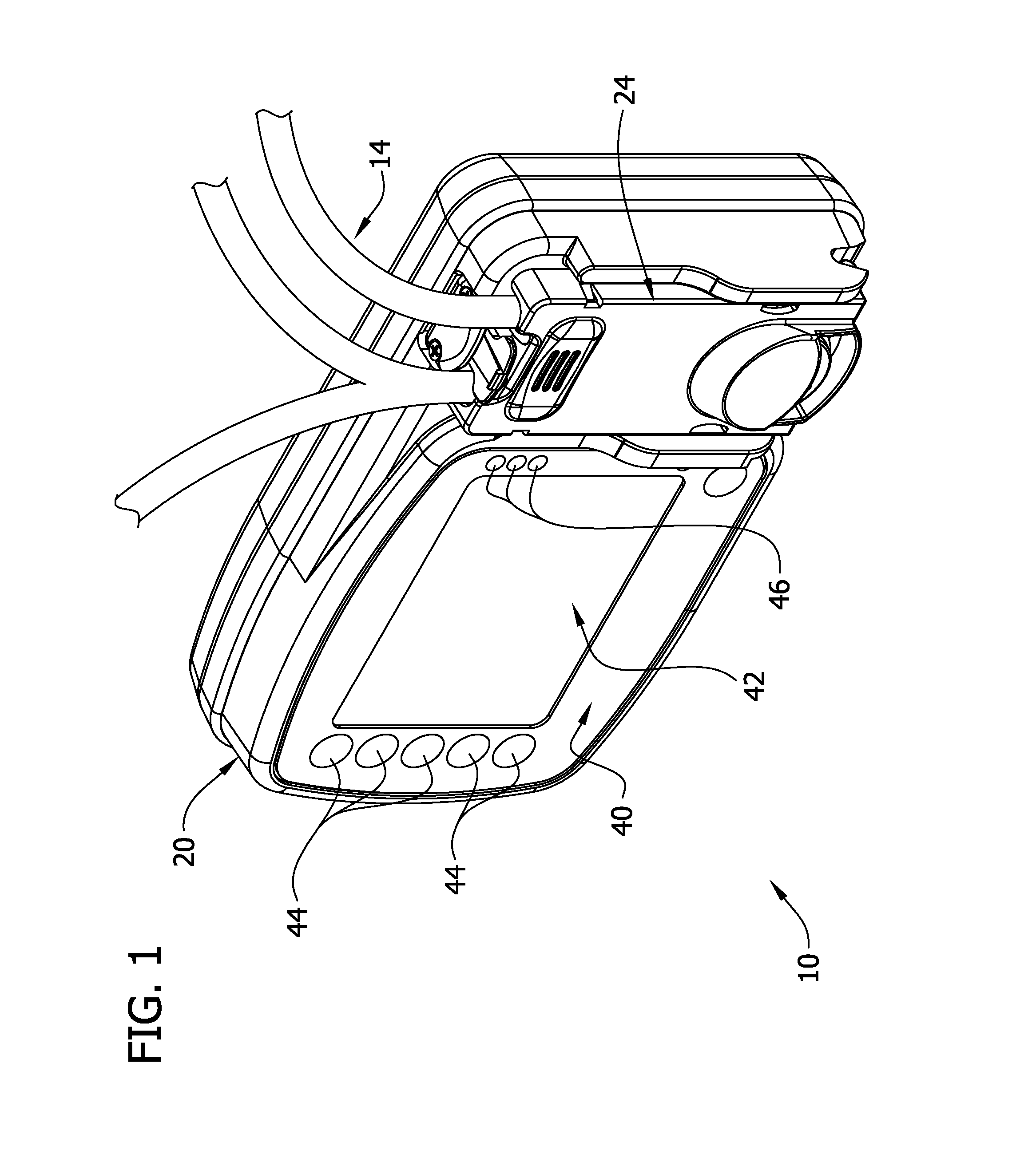
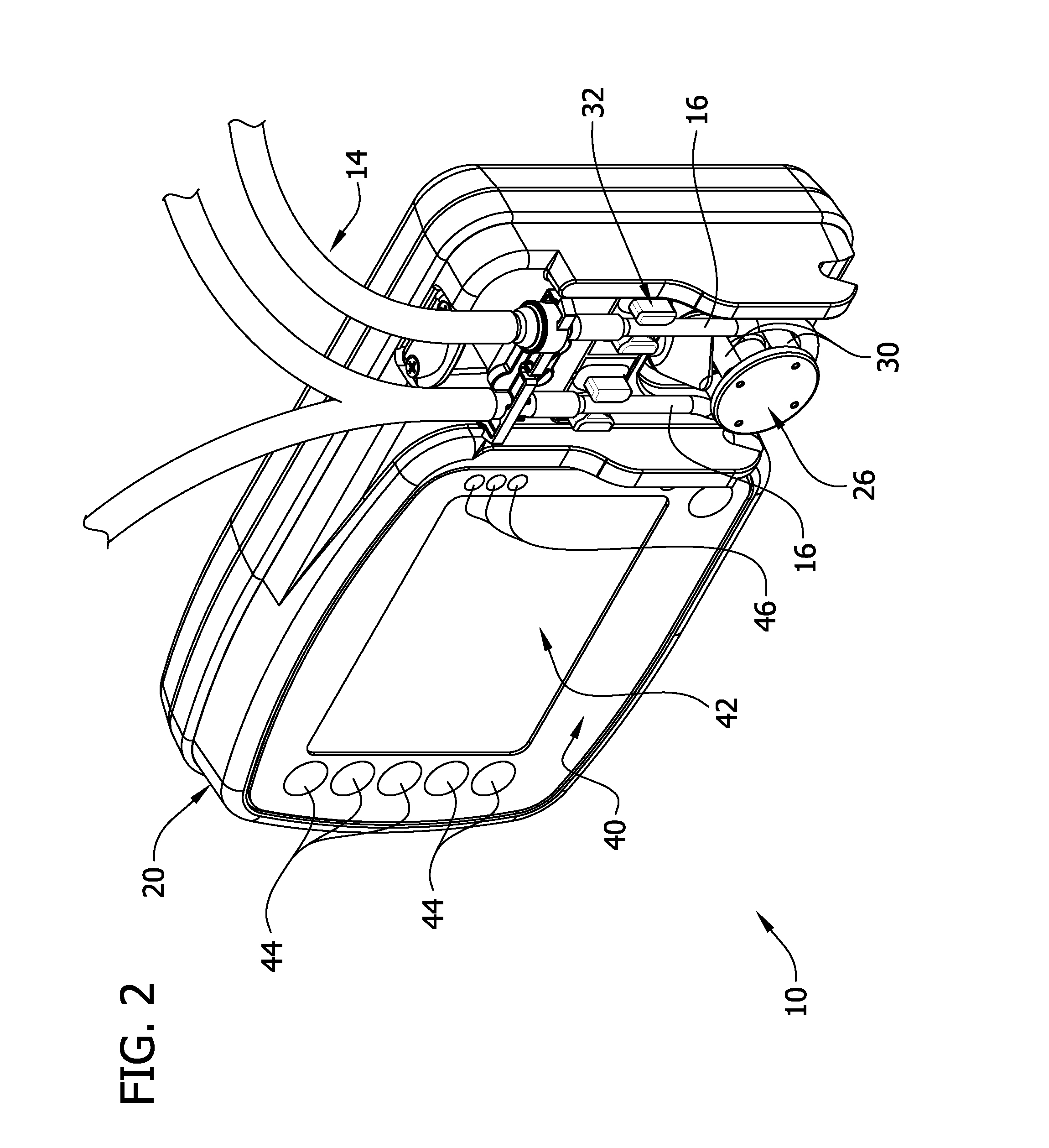
[0020]Referring to the drawings and in particular to FIGS. 1-3, an embodiment of a flow control apparatus is generally indicated at 10. The flow control apparatus may comprise a flow monitoring system 12 (FIG. 4) that is capable of detecting and identifying a flow condition present within a feeding set 14 loaded on the apparatus. The feeding set 14 may include tubing 16 that can be loaded on the flow control apparatus 10 for delivery of fluid to a patient. As used herein, the term “load” means that the tubing 16 is engaged with the flow control apparatus 10 so that the administration feeding set 14 is ready for operation with the flow control apparatus 10 to deliver fluid through the feeding set to a patient.

[0021]The flow control apparatus 10 may comprise a housing 20 adapted for loading the feeding set 14 (broadly, “pump set”) to the flow control apparatus 10. The flow control apparatus may comprise a recess 22 for receiving a cassette 24 of the feeding set 14 to load the feeding ...


PUM


Abstract

A flow control apparatus and method for accurate detection of occlusion conditions in a feeding set. A sensor is arranged with respect to a pumping device to produce a signal indicative of pressure in the feeding set. A control circuit that may receive the sensor signal from the sensor indicative of the pressure in the feeding set may also control operation of the pumping device. The control circuit is configured to operate the pumping device in an operational state, and in a reset state subsequent to the operational state in which the pumping device does not produce a pumping action and the pumping device is moved to a position in which the pumping device does not block the feeding set to permit fluid flow in a backflow direction opposite to the patient direction thereby relieving any built up pressure in the feeding set downstream of the pumping device.

Description

CROSS-REFERENCE TO RELATED APPLICATION[0001]This application claims the benefit of priority to U.S. Patent Application Ser. No. 62 / 028,970, titled FLOW DETECTION SYSTEM FOR FLOW CONTROL APPARATUS, filed on Jul. 25, 2014, which is incorporated herein by reference in its entirety for all purposes.FIELD OF THE INVENTION[0002]The present invention generally relates to a flow control apparatus capable of detecting a flow condition in a tube set mounted on the apparatus.BACKGROUND OF THE INVENTION[0003]Administering fluids containing medicine or nutrition on an ongoing basis in precise quantities to a patient is known in the art. Typically, nutritional fluid is delivered to the patient by an administration feeding set including a source of nutritional liquid that is loaded to a flow control apparatus, such as a pump that delivers fluid to the patient.[0004]A flow control apparatus of the prior art may also be capable of monitoring and detecting fluid flow conditions that can occur within ...

Claims


Application Information

Patent Timeline
IPC IPC(8): A61J15/00
CPCA61J15/0088A61J15/0076A61M5/16813A61M2005/16863A61M2205/3331A61M2205/3334A61M2205/3351A61M2205/50A61M2205/52A61M5/14232G16H20/17G16H20/13
Inventor HUDSON, JOSEPH
Owner KPR U S LLC
Learn More