Flexible tube cleaning lance drive apparatus

a drive apparatus and flexible technology, applied in the direction of metal-working feeding devices, manufacturing tools, lighting and heating apparatus, etc., can solve the problems of large and bulky drive apparatuses, and achieve the effect of reducing friction between the drive facilitating the withdrawal of the roller, and reducing the distance between the roller and the lan

Active Publication Date: 2016-01-28
STONEAGE
View PDF7 Cites 17 Cited by
  • Summary
  • Abstract
  • Description
  • Claims
  • Application Information

AI Technical Summary

Benefits of technology

[0007]The axle is a cylindrical shaft having an axial slot carrying an axial spline spaced from one end of the shaft. The roller is a generally cylindrical sleeve having an outer portion and a central bore sized to fit onto the axle shaft. This central bore includes a keyway to accommodate the axial spline carried on the axle shaft. A cross bore through the axle shaft adjacent a distal end of the shaft holds a ball nosed spring plunger. The ball projecting beyond the surface of the axle shaft prevents removal of the roller from its axle shaft. The ball can be depressed by a user to facilitate withdrawal of the roller from the axle shaft without the use of any tools.
[0008]Each pair of driven rollers coupled to the drive motor via drive axle shafts and a serpentine belt can be adjusted remotely from a control panel such that the distance between rollers may be increased or decreased to accommodate a range of flexible lance (hose) sizes. The drive mechanism incorporates an air piston to accomplish this adjustment and also provides a capability to vary the clamp force that each pair of rollers exerts on a driven flexible lance. This permits remote adjustment of the drive characteristics to overcome reduced friction between the drive rollers and the lance caused by fluid or other contaminants becoming present on the flexible lance hose and rollers during use.

Problems solved by technology

Furthermore, such drive apparatuses are large, bulky, and thus must be either separately located on a floor near the heat exchanger tube sheet into which the lance or lances are supposed to be guided, as is shown in that publication, or rigidly mounted to a tray spaced from and aligned with the tube sheet.

Method used


Image

  • Flexible tube cleaning lance drive apparatus
  • Flexible tube cleaning lance drive apparatus
  • Flexible tube cleaning lance drive apparatus

Examples


Embodiment Construction

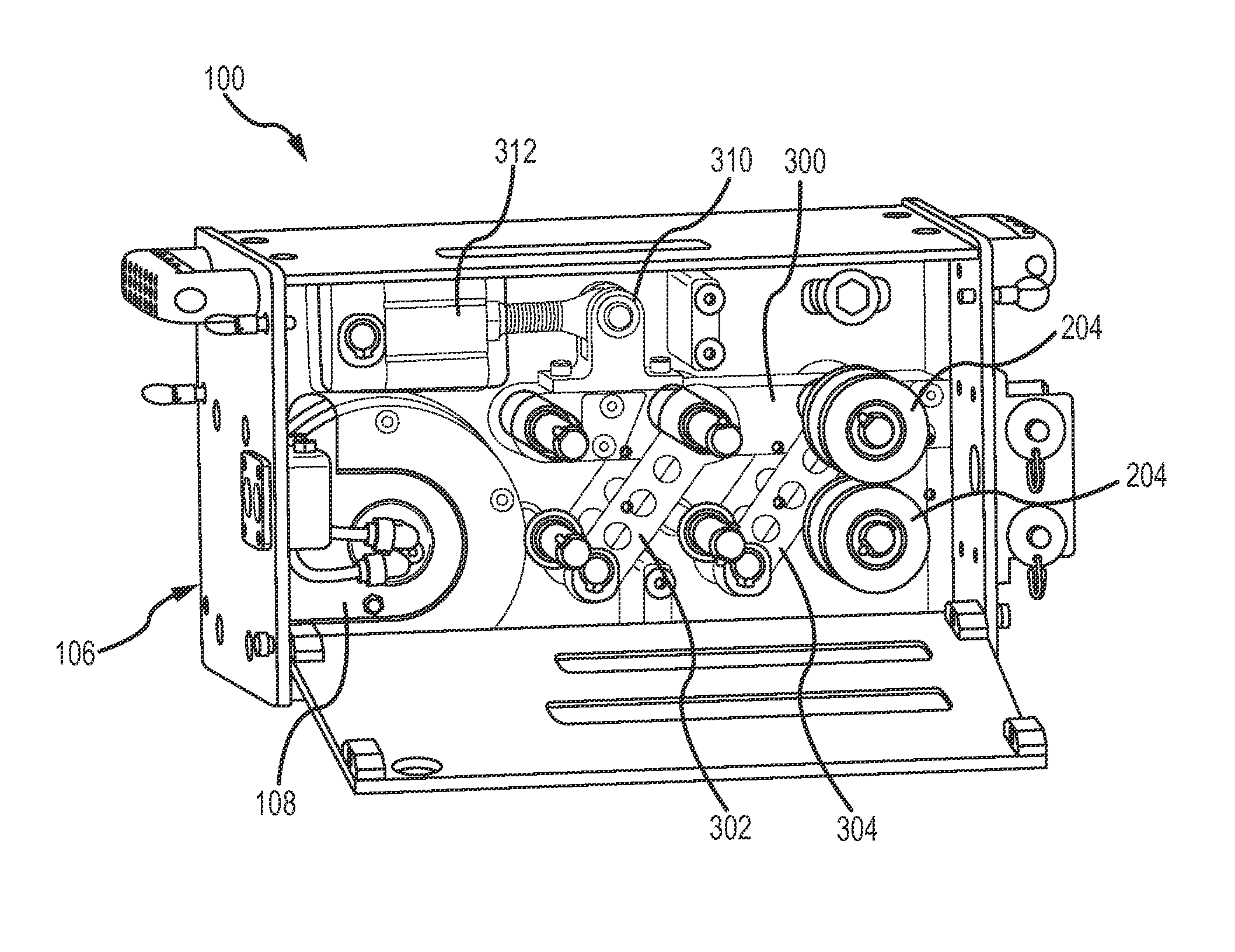
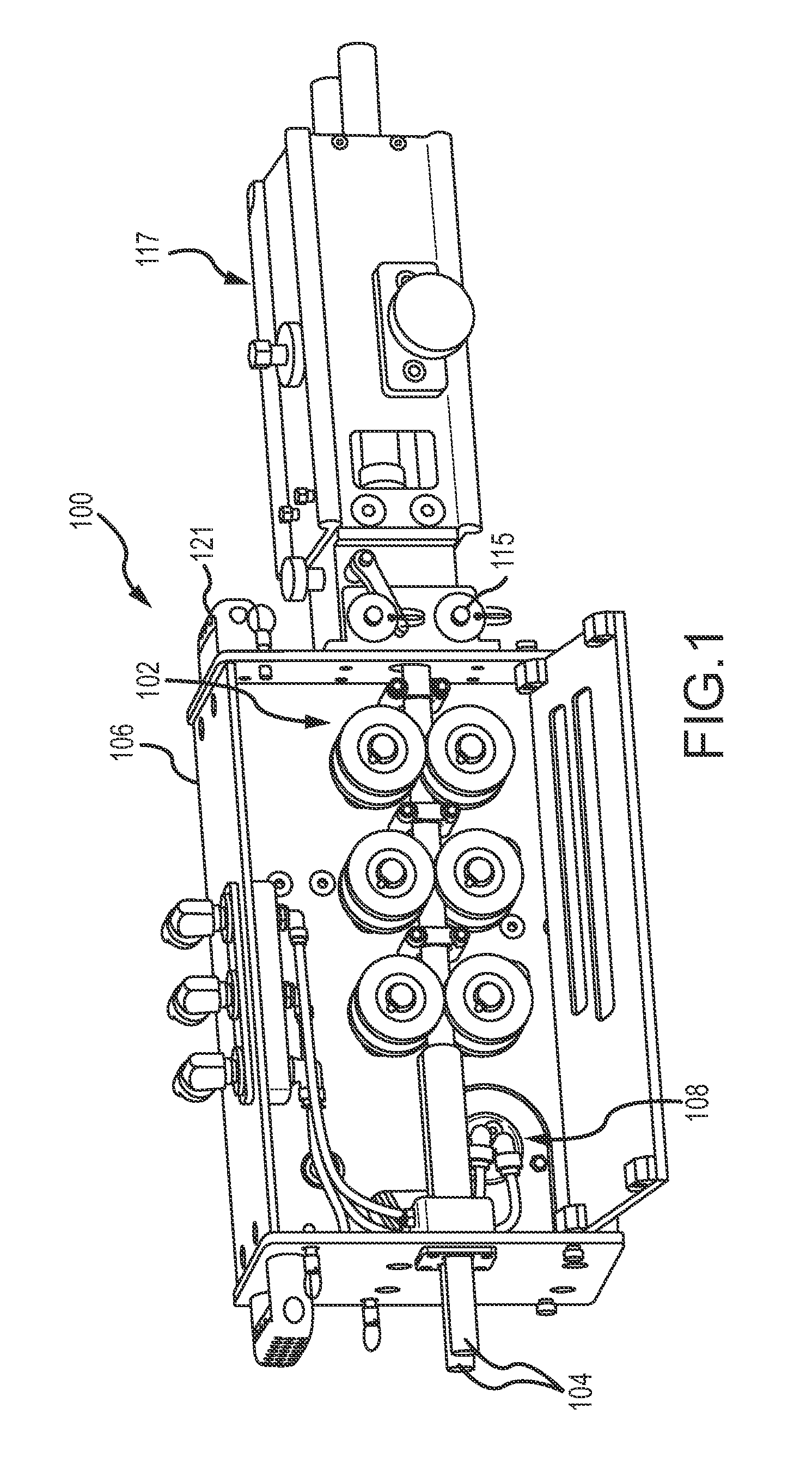
[0027]An exemplary drive apparatus 100 is shown in FIG. 1 with a side cover open showing the set of 3 pairs of drive rollers 102 arranged for driving two flexible lances 104 in accordance with one embodiment of the present disclosure. The apparatus 100 includes a housing 106 in which a drive motor 108 drives each of the six drive rollers 102.

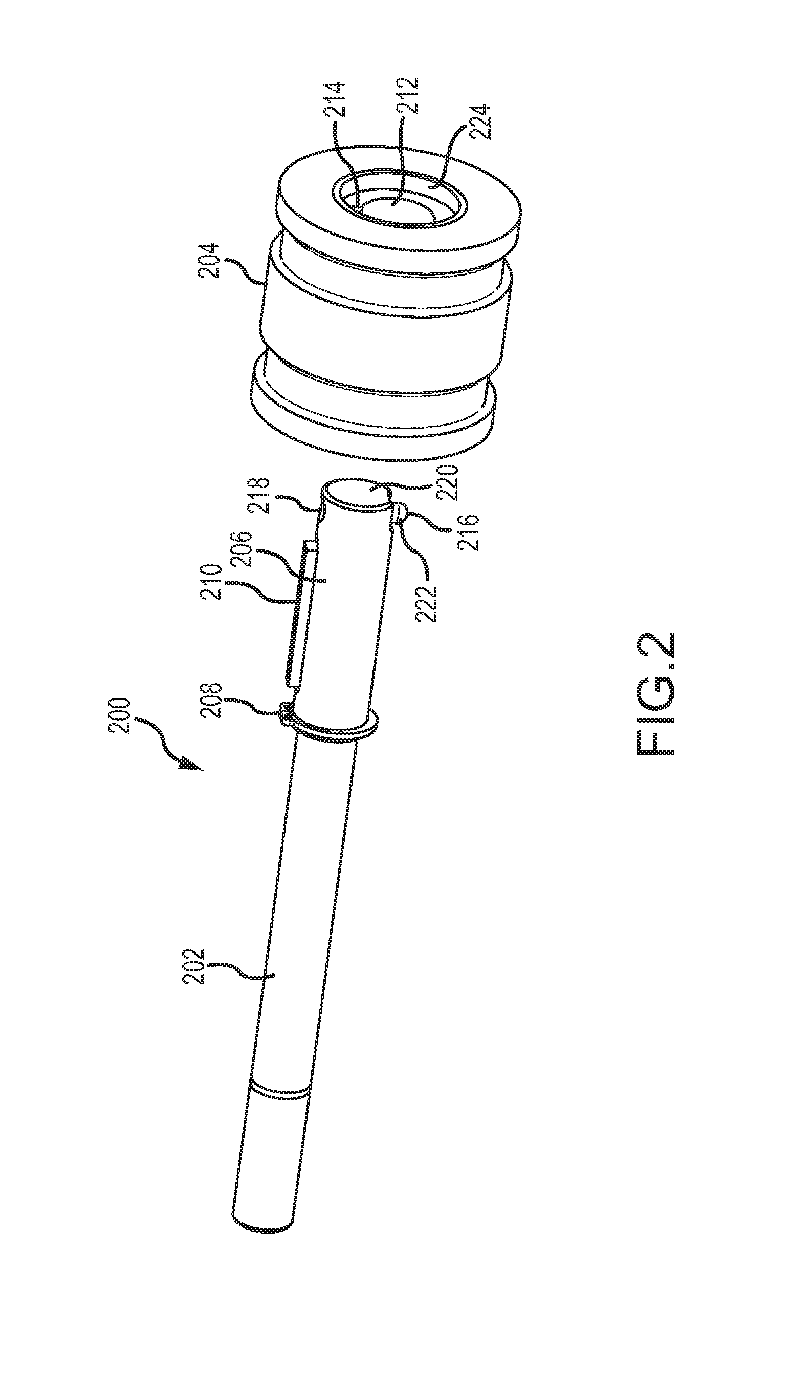
[0028]A quick change drive shaft and roller assembly 200 for use in the apparatus 100 is shown in an exploded perspective view in FIG. 2. The assembly 200 has a cylindrical axle 202 and a roller wheel 204. The axle 202 has an axially extending slot 206 extending along and spaced from a distal end of the axle 202. A snap ring 208 in a peripheral groove around the axle 202 limits how far the roller 204 can slide along the axle 202. The roller 204 has an axial bore 212 therethrough sized to slip over the axle 202. This bore 212 also has an axially extending slot 214 such that when the roller 204 is installed on the axle 202 so as to abut the snap r...


PUM


Abstract

A flexible lance drive device is disclosed that has, in a compact housing, a drive motor between an inner and an outer wall, a linear array of pairs of driven upper and lower drive rollers outside the outer wall coupled to the drive motor via shafts extending through both of the inner and outer walls. Each driven roller is fastened to its shaft via a quick release device. A drive sprocket is fastened to each shaft outside the inner wall. The drive motor is coupled to each of the drive sprockets via a serpentine belt carried outside the inner wall. The lower driven rollers are rotatably carried by the inner and outer walls. The upper driven rollers are rotatably carried by a block positioned between the inner and outer walls and coupled to the lower driven rollers by a pair of parallel links releasably biased by a piston driven linkage.

Description

CROSS REFERENCE TO RELATED APPLICATIONS[0001]This application claims the benefit of U.S. Provisional Patent Application No. 62 / 028,756, filed Jul. 24, 2014, entitled Flexible Tube Cleaning Lance Drive Apparatus Having A Quick Change Roller Device.BACKGROUND OF THE DISCLOSURE[0002]The present disclosure is directed to high pressure fluid rotary nozzle handling systems. In particular, embodiments of the present disclosure are directed to an apparatus for advancing and retracting one or more flexible tube cleaning lances from tubes arranged in an array, such as in a heat exchanger, from a position adjacent a heat exchanger tube sheet.[0003]A flexible lance drive apparatus typically includes a drive motor coupled via gearing, a chain, or a belt to one or more drive mechanisms. Drive mechanisms can be rollers that are arranged in pairs or sets sandwiching a flexible lance hose therebetween or chain and block assemblies oriented with interlocking top and bottom assemblies. At least one ro...

Claims


Application Information

Patent Timeline
Patent Type & Authority Applications(United States)
IPC IPC(8): B21D43/09
CPCB21D43/09B08B9/0433F28G3/163F28G15/02F28G15/04B65H2701/33B65H51/10B65H2402/60B65H2404/1521B65H2404/1544F28G1/163
Inventor BARNES, JEFFERY, R.
Owner STONEAGE
Why Eureka
Try Eureka