
Safety ladder and work platform for helicopter and aircraft maintenence

a safety ladder and work platform technology, applied in ladders, building construction, construction, etc., can solve the problems of not being able to position the conventional folding ladder relative to the curved body of the helicopter, not being stable when used correctly, and not being able to achieve the effect of enhancing stability

Inactive Publication Date: 2016-01-28
NEUBAUER DALE MARTIN
View PDF6 Cites 23 Cited by
  • Summary
  • Abstract
  • Description
  • Claims
  • Application Information

AI Technical Summary

Benefits of technology

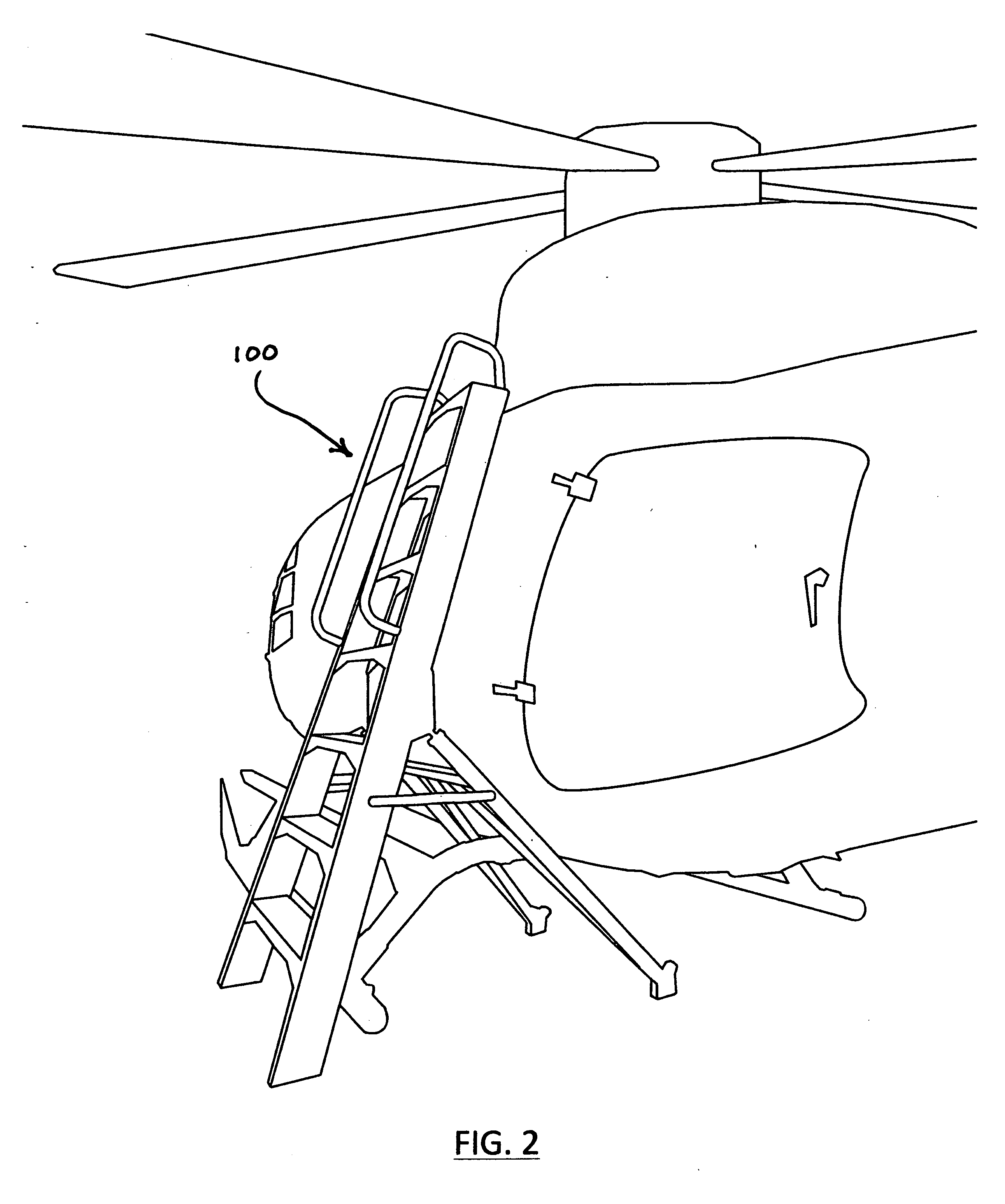
The invention is a portable ladder that can fit snugly on the curved body of a helicopter. It allows easy access to surfaces and areas that were previously difficult to reach. The ladder avoids interference with the aircraft and provides better stability than regular step ladders. Overall, it improves efficiency and safety for working at heights near a helicopter.

Problems solved by technology

Such ladders, however, are not stable.
They can be hazardous when used correctly and dangerous when used incorrectly or when a mechanic is struggling to lift a heavy part or tool.
Furthermore, a conventional folding ladder cannot be positioned relative to the curved body of a helicopter in a manner so that the mechanic is positioned in close proximity to the aircraft.
Whether placed parallel to or at an angle to the body of a helicopter, the poor fit of the ladder to the aircraft compromises the ability of the mechanic to perform his work and creates a hazardous condition when he is forced into awkward or unstable positions.
Such a design is inherently weak and can not provide the high degree of lateral stability needed in a safety work ladder.
Furthermore, the support legs will not fold flat against the stepped legs thus making the ladder excessively bulky when in its folded position.
The support legs are, of necessity, braced and cross-braced such that they cannot straddle the cross-tubes of a helicopter's skid assembly and would be unusable in many applications.

Method used


Image

  • Safety ladder and work platform for helicopter and aircraft maintenence
  • Safety ladder and work platform for helicopter and aircraft maintenence
  • Safety ladder and work platform for helicopter and aircraft maintenence

Examples


Embodiment Construction

[0028]Exemplary embodiments are discussed in detail below. While specific exemplary embodiments are discussed, it should be understood that this is done for illustration purposes only. Persons skilled in the relevant art may recognize that other components and configurations may be substituted without parting from the spirit and scope of the invention. It is to be understood that each specific element includes all equivalents that operate in a similar manner to accomplish a similar purpose

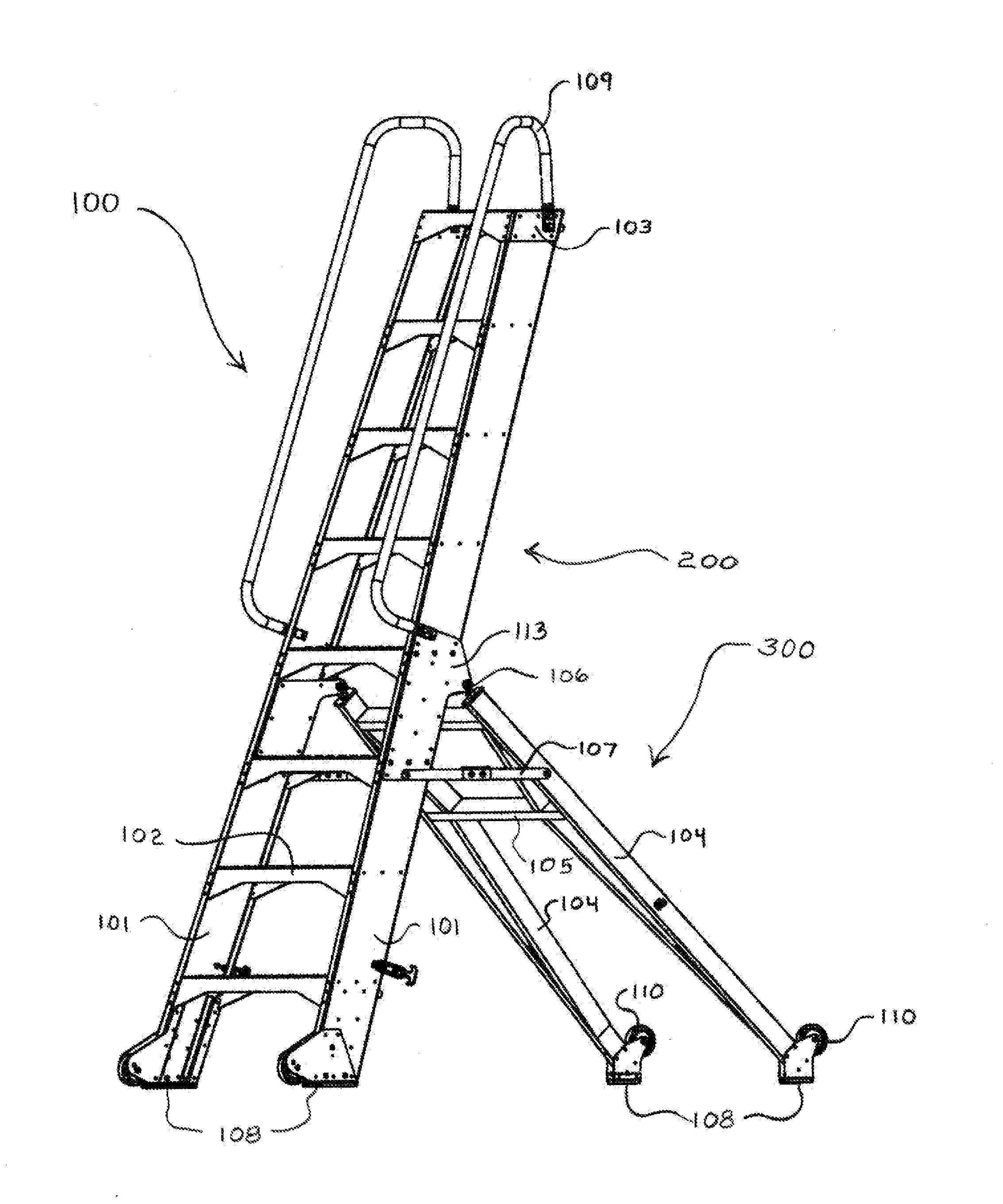
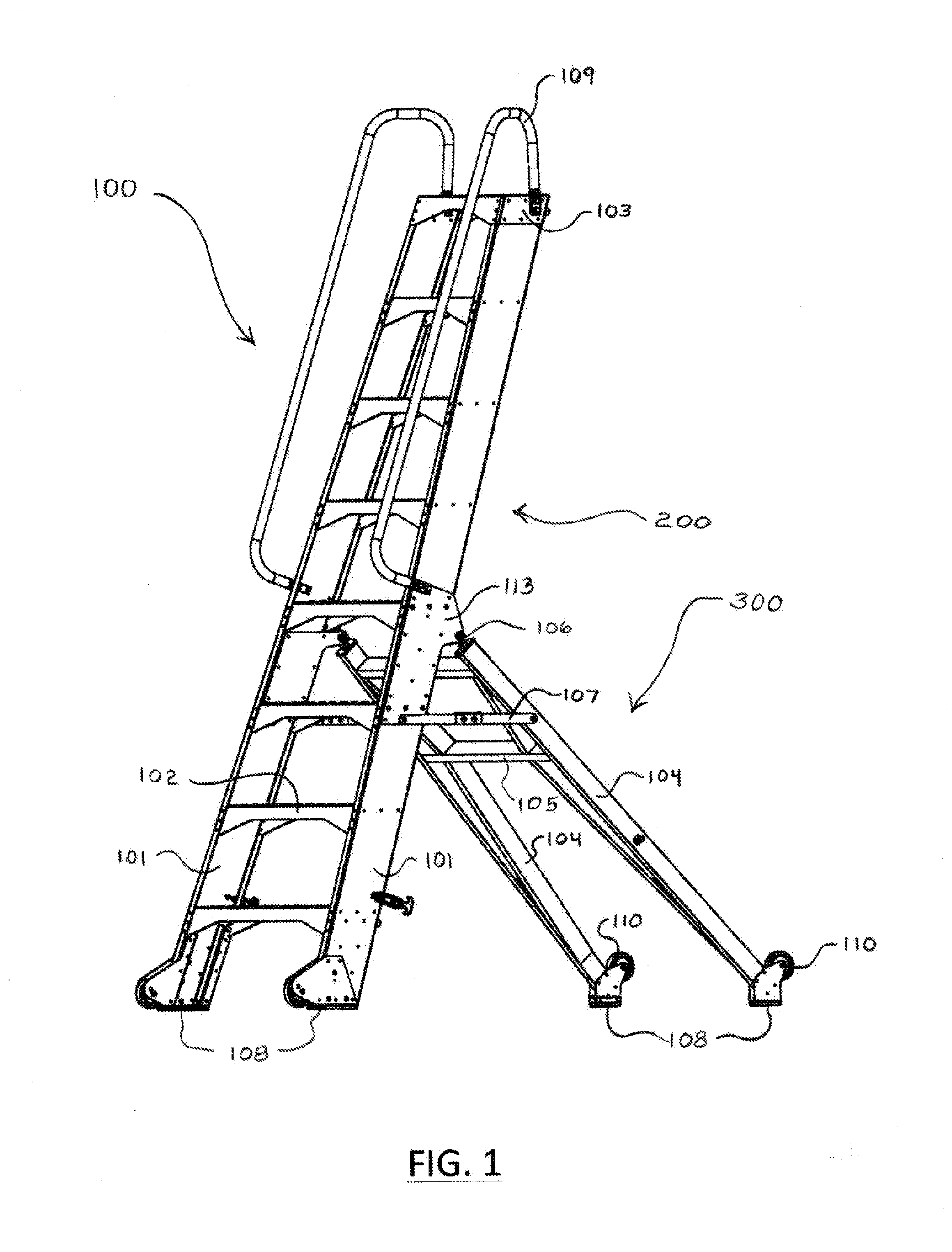
[0029]FIG. 1 Referring now to FIG. 1, a lightweight, portable, safety ladder and work platform 100 according to the first embodiment of the present invention is shown. The ladder is comprised of two pairs of rails. To one pair of rails 101 steps 102 and a top plate 103 are attached. This combination of rails, steps and top plate will be referred to as the ‘stepped unit’200. The other pair of rails 104 are braced 105 to each other as can most clearly be seen in FIG. 3. The combination of braced rail...


PUM


Abstract

The disclosed lightweight portable ladder provides a stable platform that can nest in close proximity to helicopters, aircraft and other machines to facilitate enhanced access for inspection and maintenance. The ladder consists of a stepped unit connected by hinged means located near the top a support unit and means to hold the units in a fixed orientation. The distance from the hinge point to the bottom of the support unit is longer than from the hinge point to the bottom of the stepped unit. The hinge point may be located some distance below the top of the stepped unit, in which case the upper portion of that unit will be cantilevered with respect to the hinge point. The location of the hinge point can be tailored for specific aircraft and applications so as to provide an optimized fit when the ladder is positioned for use.

Description

CROSS-REFERENCE TO RELATED APPLICATIONS[0001]This application claims the benefit of provisional patent application Ser. No. 61 / 857,589, filed Jul. 23, 2013 by the present inventor, the entirety of which is incorporated herein by reference.BACKGROUND[0002]1. Field of the Invention[0003]Embodiments of the present invention are generally directed to lightweight moveable safety ladders and work platforms and more specifically to ladders and platforms that can be placed in close proximity to helicopters and aircraft in order to provide human workers with a safe and stable means of accessing, inspecting or servicing those and similar machines.[0004]2. Statement of Prior Art[0005]Aircraft, and most especially helicopters, require regular inspection and maintenance by trained mechanics. In order to gain close access to surfaces, parts or areas higher than can be reached while standing upon the ground, it is necessary to use a ladder or work platform of adequate height.[0006]When work must b...

Claims


Application Information

Patent Timeline
Patent Type & Authority Applications(United States)
IPC IPC(8): E06C1/38E06C1/16E06C1/383
CPCE06C1/38E06C1/383E06C1/16E06C1/20E06C1/397E06C7/183E06C7/423E06C7/46
Inventor NEUBAUER, DALE, MARTIN
Owner NEUBAUER DALE MARTIN
Learn More