
Variable load control system in a hydraulic device

a hydraulic device and variable load technology, applied in the direction of machine frames, vibration dampers, machine supports, etc., can solve the problems of relative abruptness of mechanical stopping devices, limited maximum distance the piston can travel inside the housing, etc., and achieve the effect of adaptability and ease of configuration

Active Publication Date: 2016-01-28
KYB EURO GMBH SUCURSAL & NAVARRA
View PDF9 Cites 20 Cited by
  • Summary
  • Abstract
  • Description
  • Claims
  • Application Information

AI Technical Summary

Benefits of technology

The invention is a system that reduces abruptness in hydraulic devices, such as shock absorbers, by controlling the movement at the beginning and end of each stroke. The system can adapt to different applications and geometries, making it easier to configure and reduce abruptness in hydraulic devices.

Problems solved by technology

Based on the geometric limitations of the physical environment where the shock absorber operates, the maximum distance the piston can travel inside the housing (the stroke of the shock absorber) is limited.
In some applications of the shock absorber, the relative abruptness of these mechanical stopping devices can be undesirable due to lack of comfort, excessive noise, wearing out due to continued use, etc.

Method used


Image

  • Variable load control system in a hydraulic device
  • Variable load control system in a hydraulic device
  • Variable load control system in a hydraulic device

Examples


third embodiment

[0043]FIG. 6.—Shows a cross-section view of the shock absorber designed which has some differences with the previous figures.

[0044]FIG. 7.—Shows a perspective view of a modular mechanism placed within a tubular housing under a piston attached to a rod travelling in both directions along the axis inside the tubular housing while the shock absorber is operational.

[0045]FIG. 8.—Shows a perspective view of the modular mechanism also shown in the previous figure.

fourth embodiment

[0046]FIG. 9.—Shows a cross-section view of the shock absorber designed which is implemented with fewer geometric components.

DESCRIPTION OF AN EXAMPLE OF AN EMBODIMENT

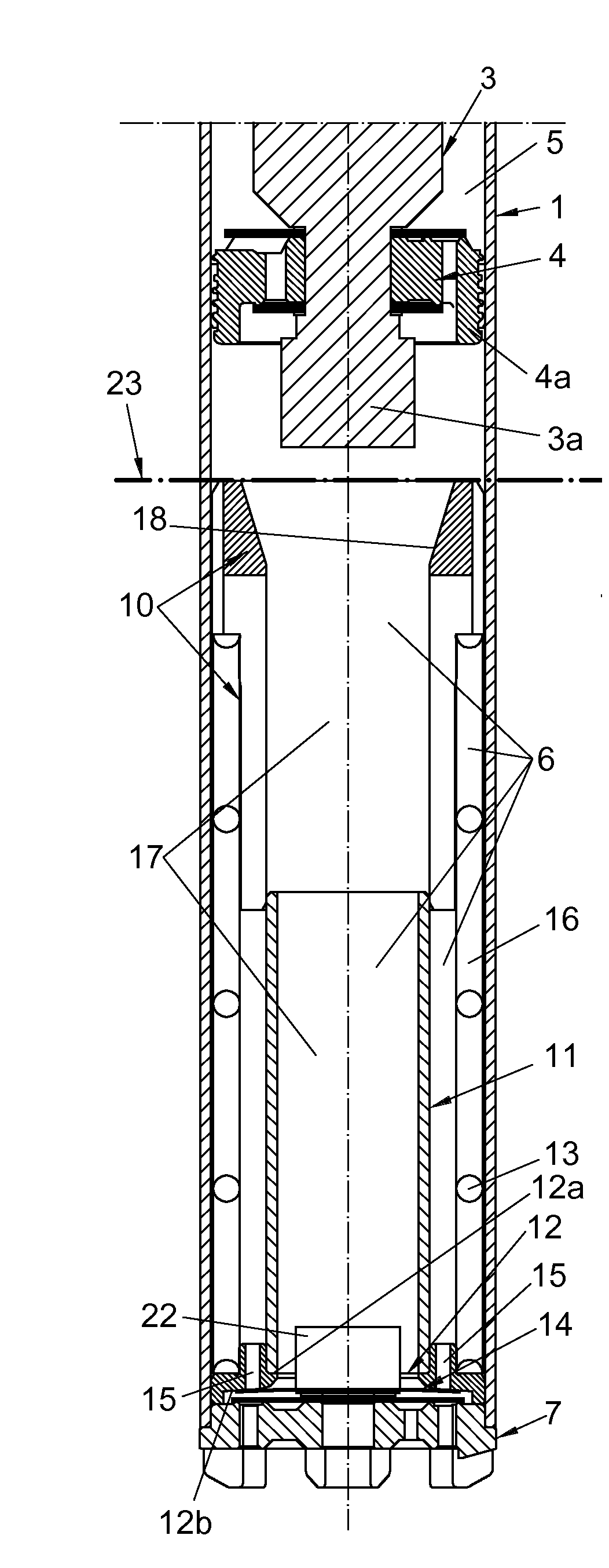
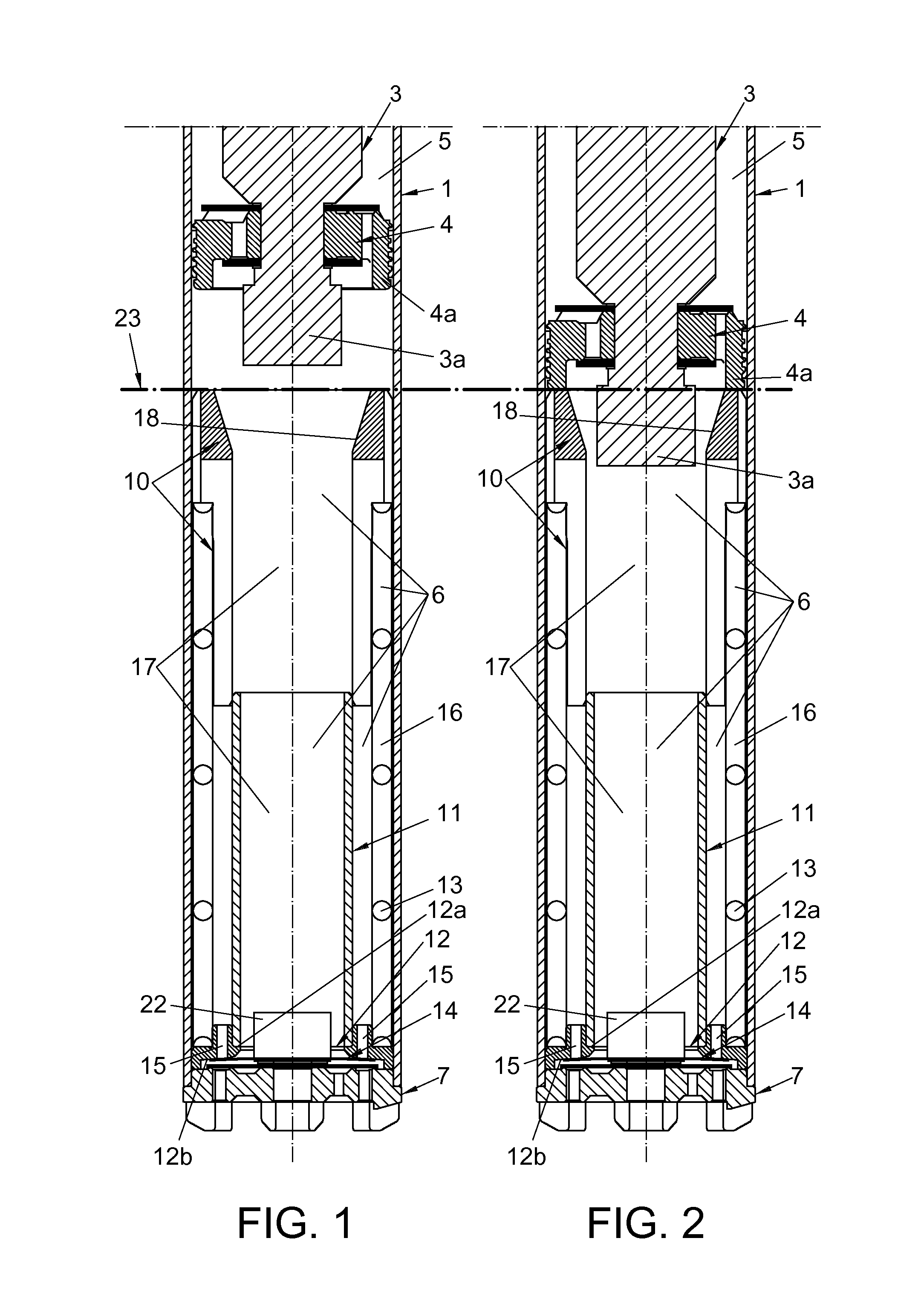
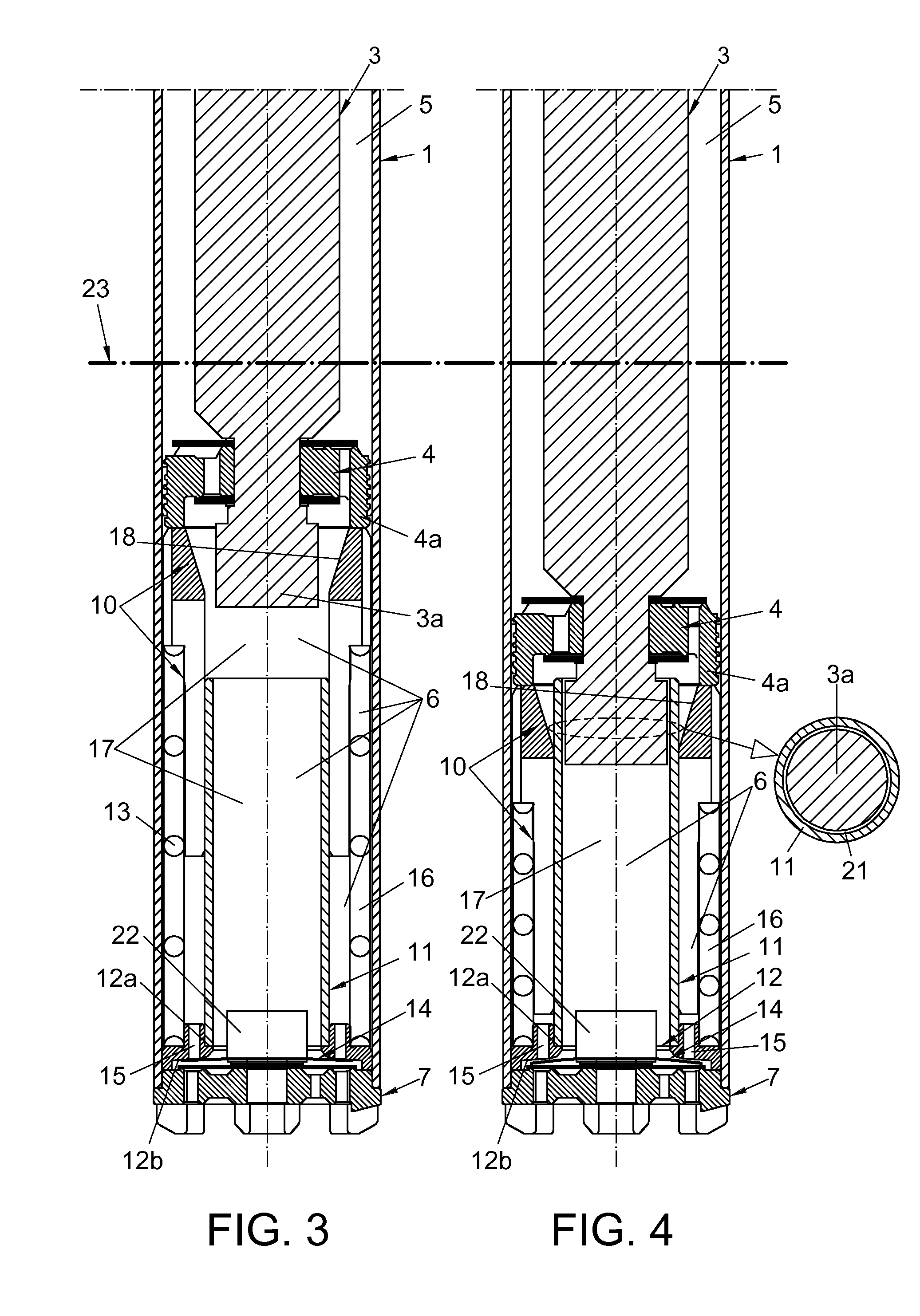
[0047]Considering the numbering adopted for the figures, the variable load control system in a hydraulic device features the following nomenclature used in the description:[0048]1.—Tubular housing[0049]2.—Modular mechanism[0050]3.—Rod[0051]3a.—Lower extension[0052]4.—Piston[0053]4a.—Perimeter skirting[0054]5.—First upper area[0055]6.—Second lower area[0056]7.—Lid[0057]8.—Through perforations (holes)[0058]9.—Annular slots[0059]10.—Upper tubular head[0060]10a.—Radial extensions[0061]11.—Lower tube[0062]12.—Annular support[0063]12a.—Upper recess[0064]12b.—Lower recess[0065]13.—Coaxial spring[0066]14.—Frontal disc[0067]15.—Through holes[0068]16.—Outer annular chamber[0069]17.—Inner chamber[0070]18.—Tapered upper mouth[0071]19.—Through slots[0072]20.—Upper tab[0073]21.—Annular passage[0074]22.—Main body[0075]23.—Upper leve...


PUM


Abstract

The hydraulic device comprises a tubular housing, inside of which a rod is jointly attached to a piston separating an upper and lower areas filled with hydraulic fluid so that, as the piston and rod move, the two components move together relatively and axially inside the tubular housing, displacing the hydraulic fluid inside the tubular housing, flowing from one area to the other, and thus changing the volumes inside said areas. It also comprises a modular mechanism located inside the lower area that regulates the shock absorption at the maximum level of compression of the hydraulic device, as well as in other relative positions.

Description

OBJECT OF THE INVENTION[0001]The present invention, as described in the title of this description, refers to a variable load control system in a hydraulic device that aims to regulate hydraulic load development during at least any of the periods when the device is operational.[0002]The system is applicable to hydraulic devices such as shock absorbers, helping reduce problems of abruptness resulting after a first stroke ending at maximum compression and also during a second stroke ending at maximum extension, so that the reduction in abruptness is controlled especially at the end of each stroke, the first and the second, of the hydraulic device.[0003]Therefore, the system of the invention aims to provide shock absorption for the hydraulic device, said absorption depending on the length of the shock absorber at each moment, and depending on the linear velocity of the shock absorber when it is active, both when it is moving towards maximum extension as well as when it is moving in the ...

Claims


Application Information

Patent Timeline
IPC IPC(8): F16F9/19F16F9/348F16F13/00
CPCF16F9/19F16F9/348F16F13/007F16F9/49F16F9/3214
Inventor LIZARRAGA, SENAR, JAVIER
Owner KYB EURO GMBH SUCURSAL & NAVARRA
Learn More