Emergency exit sign

Active Publication Date: 2016-01-28
EVACLITE LTD
View PDF13 Cites 22 Cited by
  • Summary
  • Abstract
  • Description
  • Claims
  • Application Information

AI Technical Summary

Benefits of technology

[0029]Preferably, the sign comprises perforated printing. Preferably, the perforated printing is

Problems solved by technology

Most of these signs are either constantly illuminated or illuminate upon power failure.
In the main, these type of signs are adequate when they are seen by people during an evacuation; however rec

Method used


Image

  • Emergency exit sign
  • Emergency exit sign
  • Emergency exit sign

Examples


embodiment 1

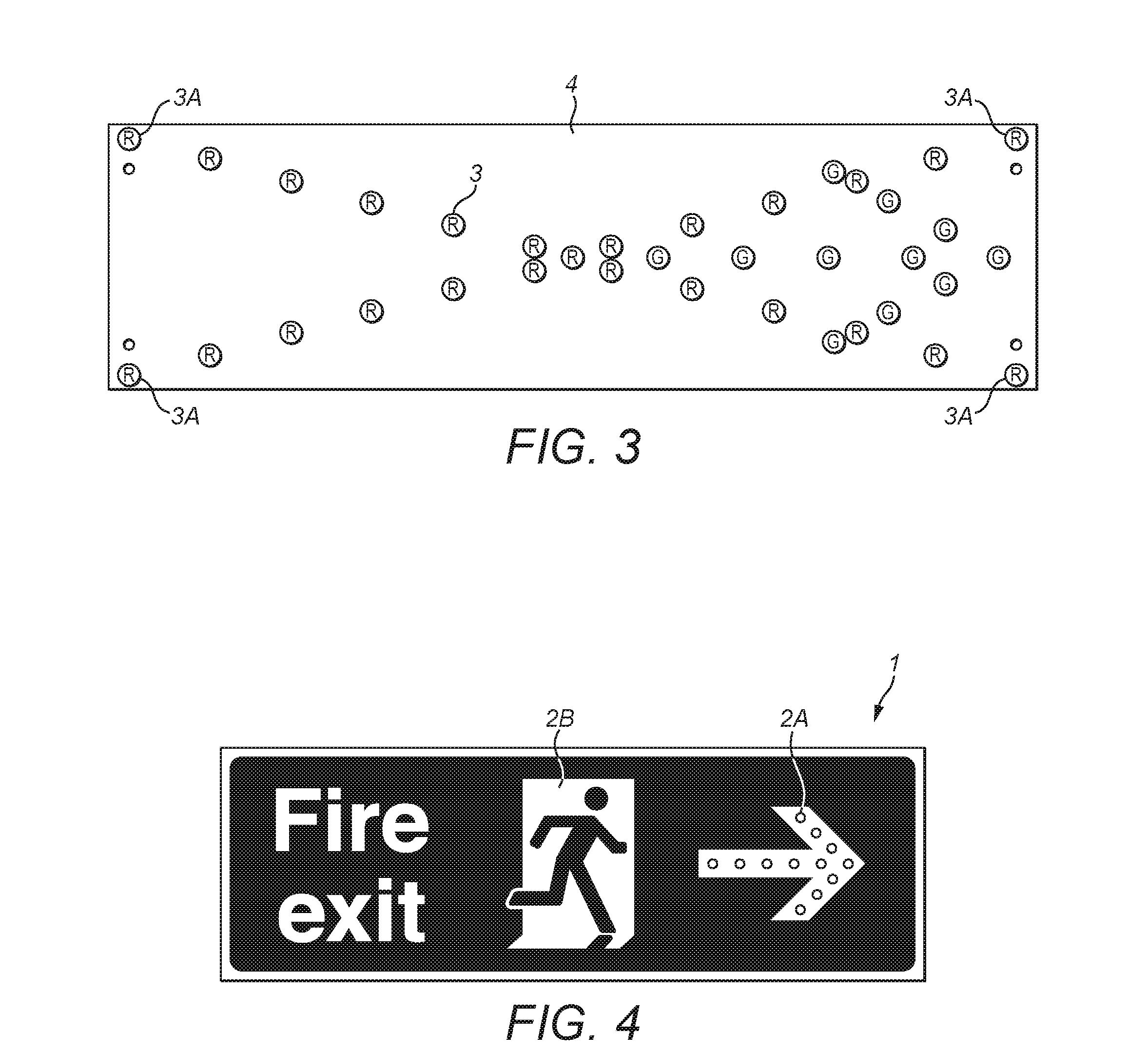
2. The LEDs , which either flash or chase to create a moving arrow in the required direction or static / pulsating red cross to stop / hold an exit from use.

embodiment 2

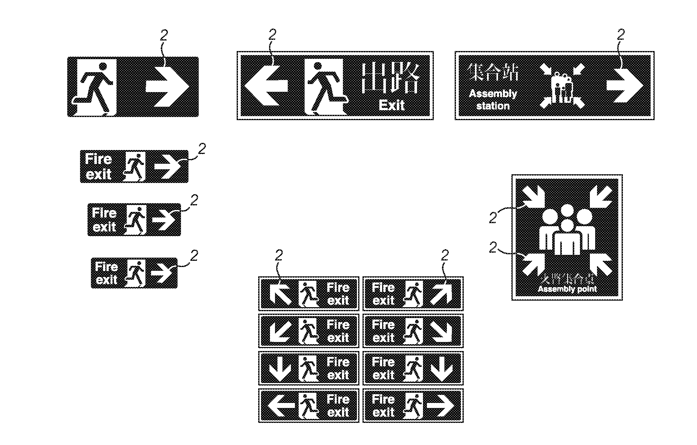
3. The invention , which can also be multi directional with the arrow directing up / down or / left / right and / or diagonally up left / right or diagonally down left / right.

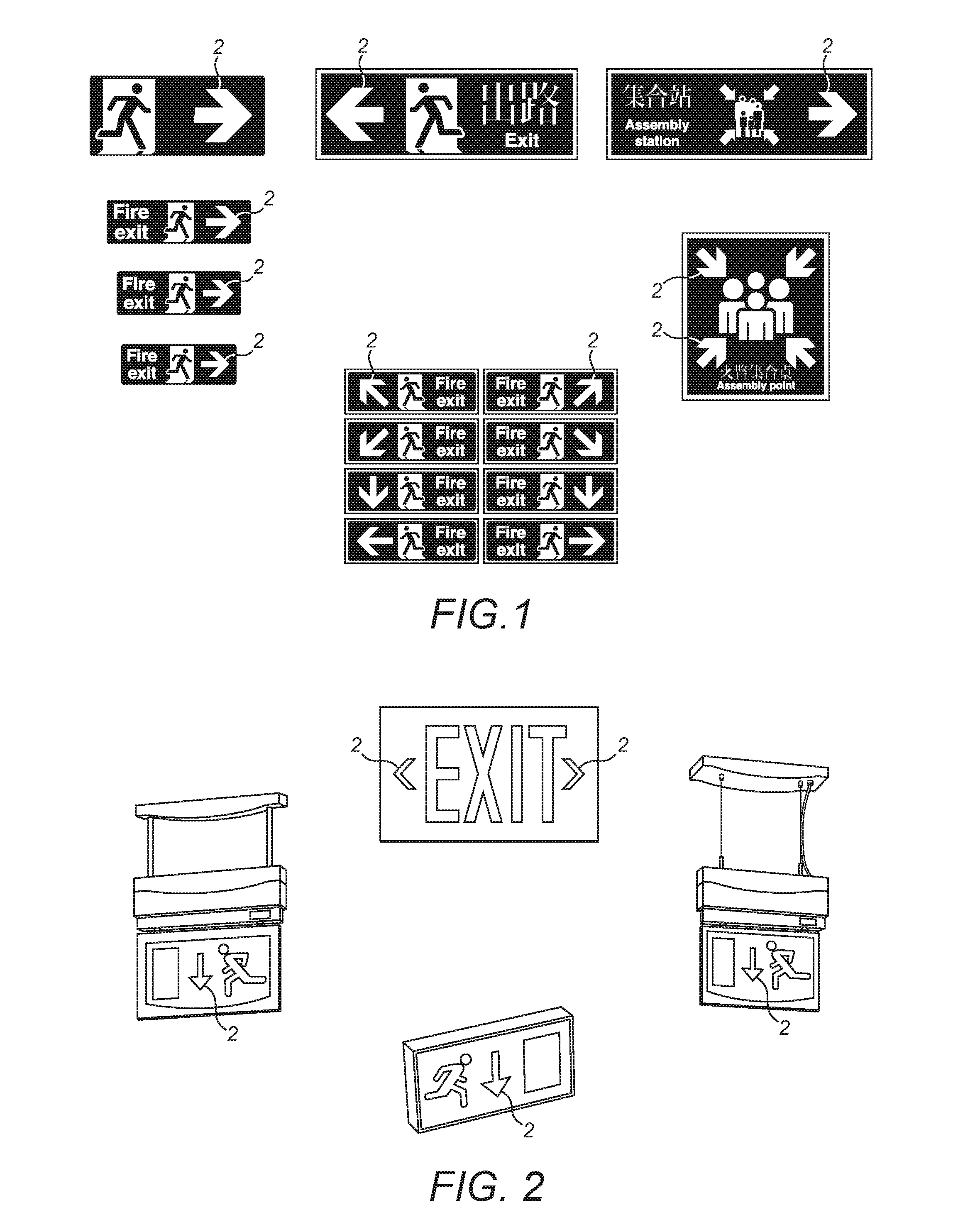
4. The invention according to any of the preceding embodiments which can also be manufactured as a complete Fire Emergency Escape Route / Exit sign or retrofitted into existing signs.

[0126]This invention addresses the problem of recent studies which show that present day emergency escape signage is not as effective as it could be. Present signs show the direction to the nearest exit however most importantly they do not enable a change of direction should the circumstances deteriorate during an evacuation.

[0127]This invention increases the affordance of the sign by the use of a matrix of LEDs embedded into a printed circuit board and forming the shape of the pictogram arrow present in British & European Exit Signs, with the addition of further LEDs forming a cross which tell the evacuee not to proceed past this sign. This i...


PUM


Abstract

Described is a dynamic emergency exit sign comprising one or more pictograms and at least one light source for accentuating one or more of the one or more pictograms either singly or in combination, wherein at least one light source is controlled by signals from evacuation computer modelling software to assist occupants egress in emergency or other critical situations.

Description

[0001]The present invention relates to emergency exit signs, in particular to emergency exit signs adapted for providing more effective information in the event of an emergency.[0002]Illuminated fire exit signs seen in public buildings and offices around the world are used to identify the fire evacuation exit routes and a final exit. These signs conform to various international codes such as ISO7010 / ISO3864-1 and UL924. Most of these signs are either constantly illuminated or illuminate upon power failure. They show pictogram type symbols such as a running man, a door and an arrow or the word EXIT and chevrons depicting the route to take during an emergency. Most of these signs are required under these codes to exhibit a specific amount of illumination and to provide an emergency back-up power source for a specified period of time should the power fail. In the main, these type of signs are adequate when they are seen by people during an evacuation; however recent academic studies ha...

Claims


Application Information

Patent Timeline
IPC IPC(8): G08B7/06
CPCG08B7/062G08B7/066G09F13/04G09F19/22G09F2019/225G09F2013/05
Inventor MC DONAGH, BERNARDSTEVENS, BRIAN
Owner EVACLITE LTD
Why Eureka
Try Eureka