Assembled conductor and manufacturing method for assembled conductor

a technology of assembled conductors and manufacturing methods, which is applied in the direction of conductors, non-insulated conductors, and reduction of cables/conductors, etc., can solve the problems that the insulation film b>803/b> cannot have the thickness required in order, and achieve the effect of suppressing twist deformation and suppressing torsion

Inactive Publication Date: 2016-01-28
TOYOTA JIDOSHA KK
View PDF12 Cites 4 Cited by
  • Summary
  • Abstract
  • Description
  • Claims
  • Application Information

AI Technical Summary

Benefits of technology

[0023]Gripping force (for example, chucking force) for gripping the conductor bundle when twisting the peripheral conductor may be strong enough to twist the peripheral conductor while maintaining a state where the peripheral conductor is separated from the central conductor when the conductor bundle is gripped.
[0024]According to this structure, it is possible to twist the peripheral conductor while suppressing torsion.
[0025]According to the invention, it is possible to provide an assembled conductor that suppresses twist deformation, and a manufacturing method for the assembled conductor.

Problems solved by technology

Therefore, there is a possibility that the insulating film 803 is not able to have a thickness required in order to function as a film.

Method used


Image

  • Assembled conductor and manufacturing method for assembled conductor
  • Assembled conductor and manufacturing method for assembled conductor
  • Assembled conductor and manufacturing method for assembled conductor

Examples


first embodiment

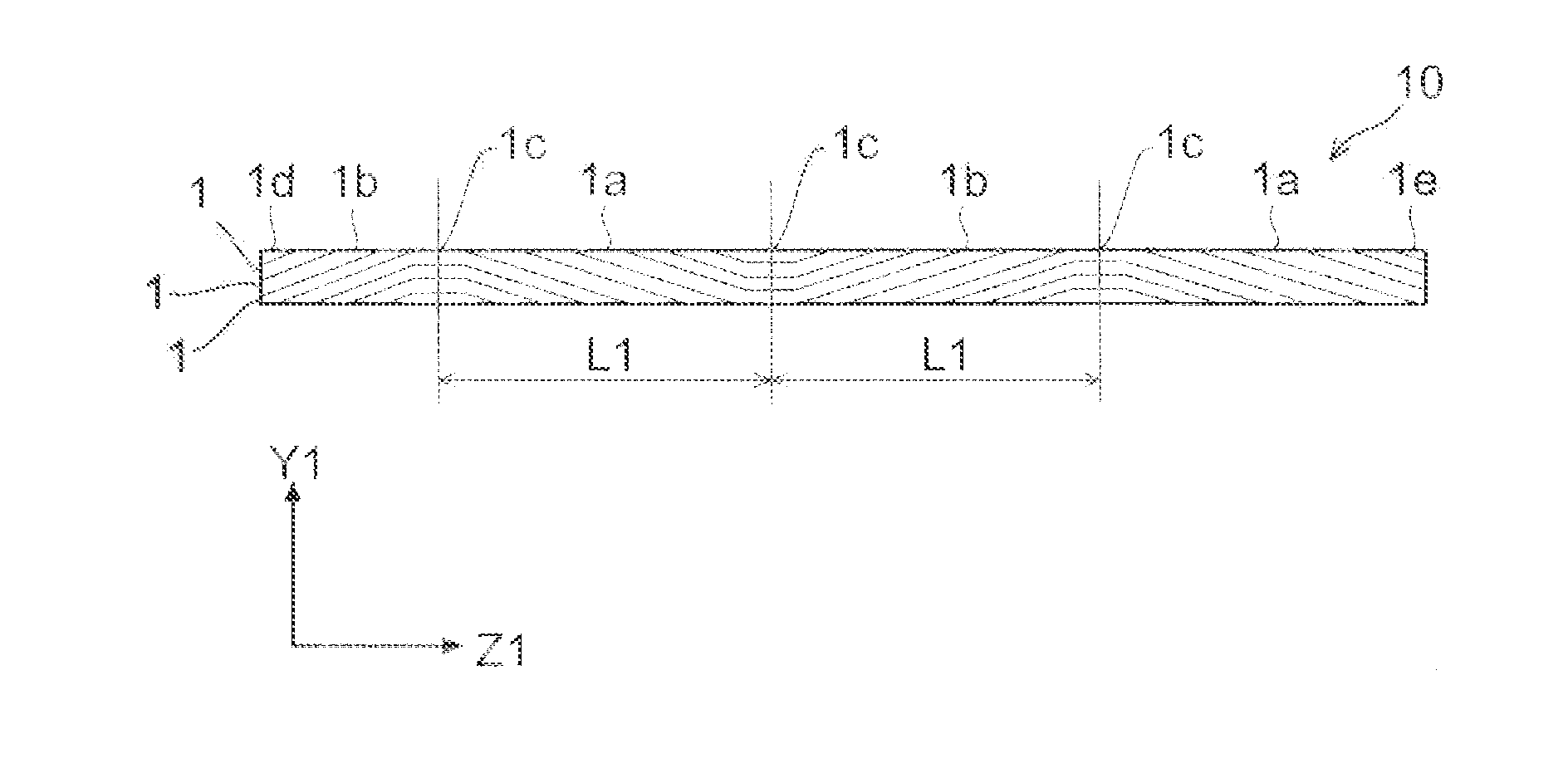
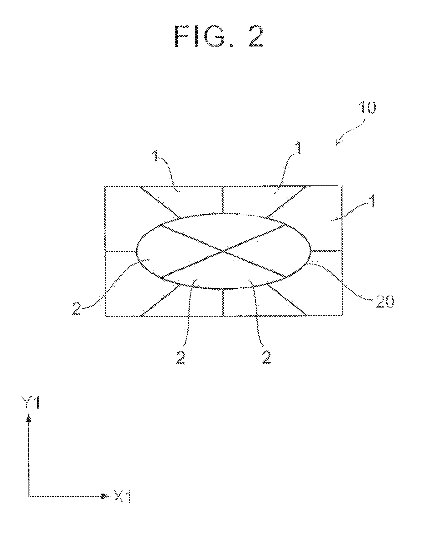
[0042] (Assembled conductor) Referring to FIG. 1 to FIG. 4, an assembled conductor according to the first embodiment is explained. FIG. 1 is a side view of an assembled conductor according to the first embodiment. FIG. 2 is a sectional view of the assembled conductor according to the first embodiment. FIG. 3 is a side view of a central conductor according to the first embodiment. FIG. 4 is a sectional view of the central conductor according to the first embodiment. In FIG. 2 and FIG. 4, hatching is omitted as appropriate for simplicity.

[0043]As shown in FIG. 1 and FIG. 2, an assembled conductor 10 includes a central conductor bundle 20, and peripheral conductors 1 arranged around the central conductor bundle 20. The assembled conductor 10 is, for example, a linear body having a given sectional shape such as a rectangular section. The sectional shape of the assembled conductor 10 may be formed by rolling as described later.

[0044]As shown in FIG. 3 and FIG. 4, the central conductor bu...

experiment 1

[0066]Experiment 1 and experiment 2 were carried out by using the manufacturing method according to the first embodiment. One conductor was used as the twisted central conductor bundle 104, and eight conductors having trapezoidal sections were used as the peripheral wires 106. To be specific, experiment 1 was carried out where chucking force at the clamps 149, 151, and the rotating machine 150 in the peripheral wire twisting step S8 was an experimental factor. Further, experiment 2 was carried out where a diameter of the twisted central conductor bundle 104 in the above-mentioned manufacturing method according to the first embodiment was an experimental factor.

[0067](Upper limit value of the preferred diameter of the central conductor) In experiment 1, in a state where the clamps 149, 151 and the rotating machine 150 gripped the conductor bundle 107 with given chucking force Fc, a maximum value Trmax of twisting toque was measured, by which the conductor bundle 107 could be twisted ...


PUM

PropertyMeasurementUnit
twist angleaaaaaaaaaa
central angleaaaaaaaaaa

Abstract

The invention provides an assembled conductor, which is formed by rolling a conductor bundle including a central conductor and a peripheral conductor arranged around the central conductor. The central conductor has a shape in which a right-twisted portion of the central conductor and a left-twisted portion of the central conductor are arranged alternately in predetermined intervals. The right-twisted portion of the central conductor extends from one end side of the central conductor to the other end side of the central conductor and is twisted in a clockwise direction, and the left-twisted portion of the central conductor extends from the one end side of the central conductor to the other end side of the central conductor and is twisted in a counterclockwise direction. The peripheral conductor is arranged around the central conductor so that a twist direction of the peripheral conductor becomes opposite to a twist direction of the central conductor.

Description

INCORPORATION BY REFERENCE[0001]The disclosure of Japanese Patent Application No. 2014-148796 filed on Jul. 22, 2014 including the specification, drawings and abstract is incorporated herein by reference in its entirety.BACKGROUND OF THE INVENTION[0002]1. Field of the Invention[0003]The invention relates to an assembled conductor and a manufacturing method for the assembled conductor. The invention relates especially to an assembled conductor, which is formed by rolling a conductor bundle including a central conductor and a peripheral conductor arranged around the central conductor, and to a manufacturing method for the assembled conductor.[0004]2. Description of Related Art[0005]There is an assembled conductor that is formed by bundling conductors. Japanese Patent Application Publication No. 2009-199749 (JP 2009-199749 A) discloses a manufacturing method for an assembled conductor. In the technique disclosed in JP 2009-199749 A, a plurality of wires is stranded together, thus formi...

Claims


Application Information

Patent Timeline
Patent Type & Authority Applications(United States)
IPC IPC(8): H01B5/00H01B13/00
CPCH01B13/0036H01B5/002B21C37/047B21F7/00H01B13/0006H01B13/0285
Inventor MIZUSHIMA, DAISUKEADACHI, HIRONARIINOSHITA, HIROFUMI
Owner TOYOTA JIDOSHA KK
Why Eureka
Try Eureka