Pin Diode and Manufacturing Method Thereof, and X-Ray Detector Using Pin Diode and Manufacturing Method Thereof

a technology applied in the field of pin diodes and manufacturing methods, and x-ray detectors using pin diodes, can solve the problems of deteriorating the performance of x-ray detectors, affecting the operation of x-ray detectors, etc., and achieve the effect of maximizing the fill factor of the pin diodes

Active Publication Date: 2016-01-28
HYDIS TECH
View PDF4 Cites 3 Cited by
  • Summary
  • Abstract
  • Description
  • Claims
  • Application Information

AI Technical Summary

Benefits of technology

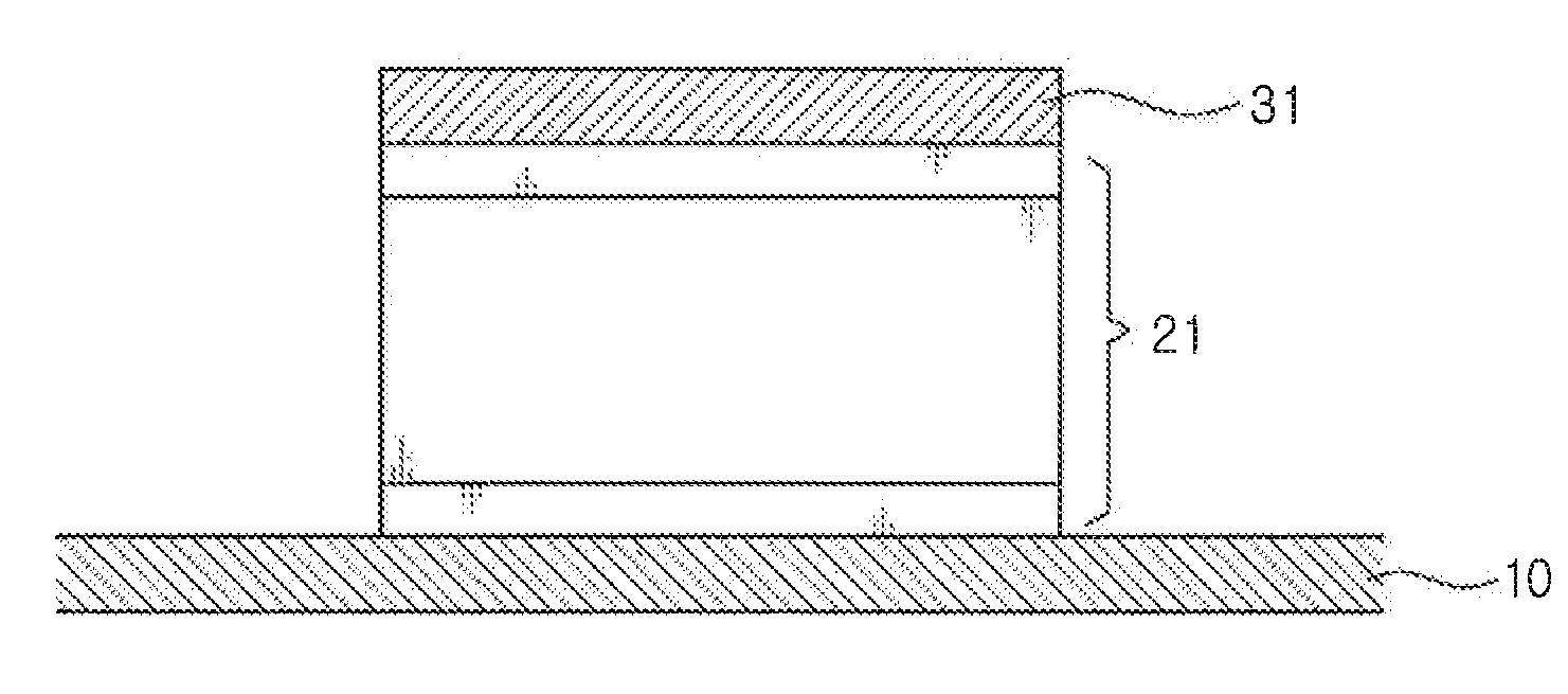
[0046]Various aforementioned aspects of the present disclosure have an effect of providing a PIN diode wherein a size of an upper electrode of the PIN diode is formed such that it corresponds to a size of a PIN structure thereby maximizing a fill factor of the PIN diode, and a manufacturing method thereof, and an x-ray detector using the PIN diode and a manufacturing method thereof.
[0047]Various aforementioned aspects of the present disclosure have another effect of providing a PIN diode wherein an upper electrode is deposited above the PIN diode at a high temperature thereby preventing the upper electrode from coming off, and a manufacturing method thereof, and an x-ray detector using the PIN diode and a manufacturing method thereof.

Problems solved by technology

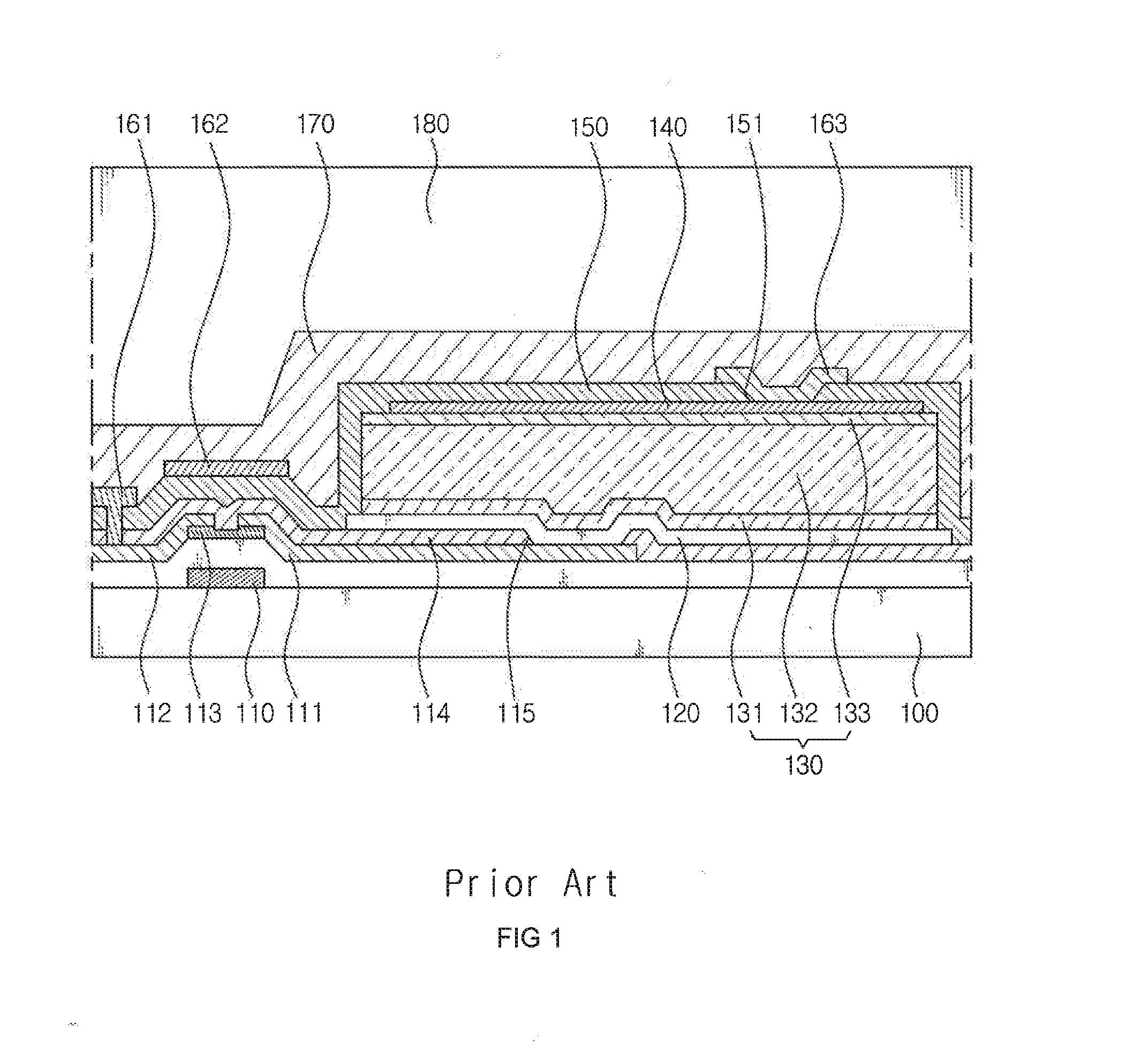
The smaller the fill factor, the smaller the amount of conversion into electrical signals even with a same amount of visible rays, thereby deteriorating the performance of the x-ray detector.
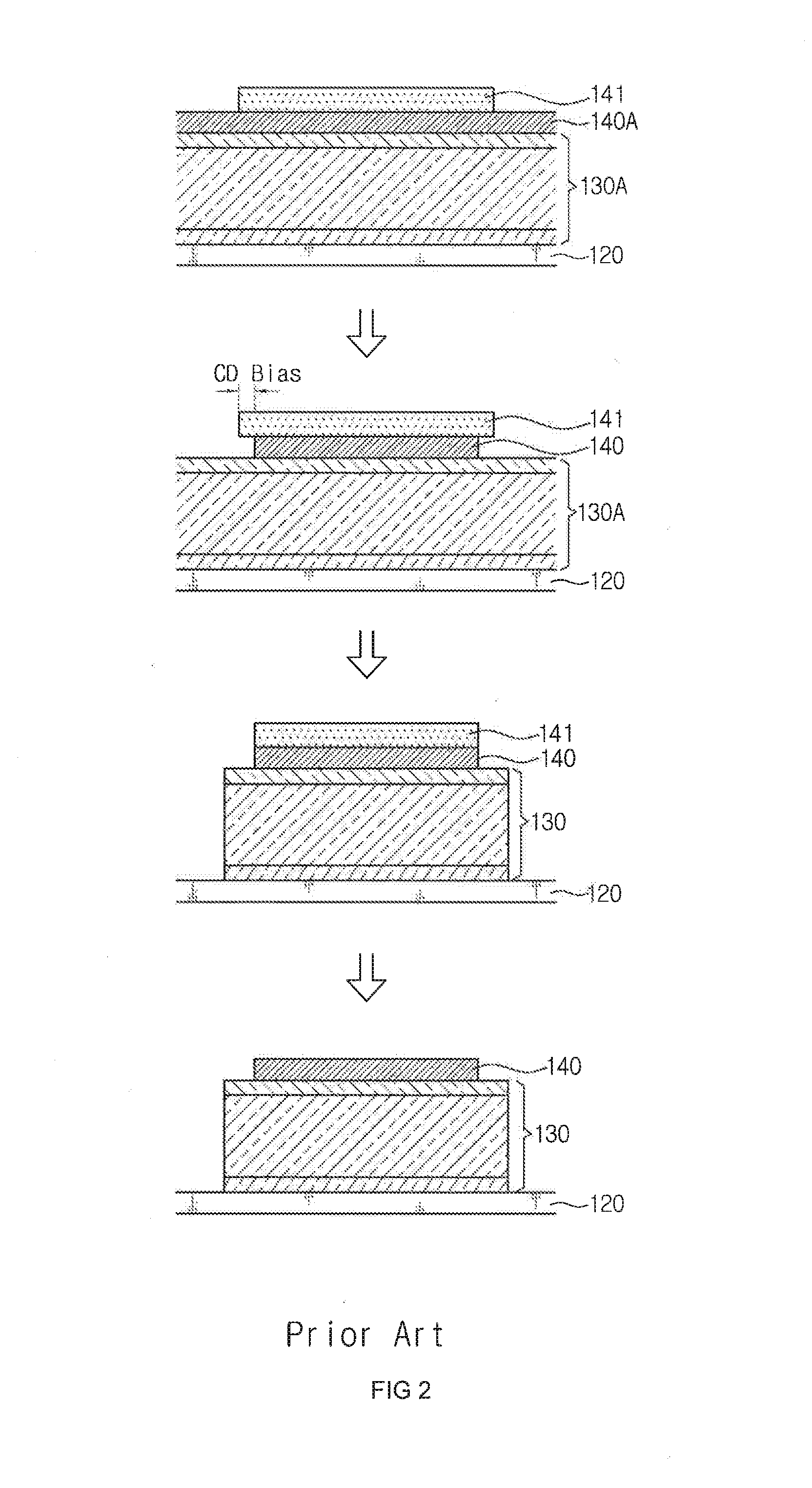
Meanwhile, since the upper electrode 140 is deposited at a room temperature, it is problematic in that its adhesive force with the PIN structure 130 is low, thereby causing the upper electrode 140 to come off in a subsequent process.
Meanwhile, besides the said x-ray detector, any apparatus where a PIN diode structure including a lower electrode, PIN structure, and upper electrode is applied may have the same problem.

Method used


Image

  • Pin Diode and Manufacturing Method Thereof, and X-Ray Detector Using Pin Diode and Manufacturing Method Thereof
  • Pin Diode and Manufacturing Method Thereof, and X-Ray Detector Using Pin Diode and Manufacturing Method Thereof
  • Pin Diode and Manufacturing Method Thereof, and X-Ray Detector Using Pin Diode and Manufacturing Method Thereof

Examples


Embodiment Construction

[0052]The following detailed description is provided to assist the reader in gaining a comprehensive understanding of the methods, apparatuses, and / or systems described herein. However, various changes, modifications, and equivalents of the systems, apparatuses, and / or methods described herein will be apparent to one of ordinary skill in the art. The progression of processing steps and / or operations described is an example; however, the sequence of and / or operations is not limited to that set forth herein and may be changed as is known in the art, with the exception of steps and / or operations necessarily occurring in a certain order. Also, descriptions of functions and constructions that are well known to one of ordinary skill in the art may be omitted for increased clarity and conciseness

[0053]The features described herein may be embodied in different forms, and are not to be construed as being limited to the examples described herein. will be thorough and complete, and will convey...


PUM


Abstract

Provided herein is a PIN diode, a manufacturing method thereof, an x-ray detector using the PIN diode, and a manufacturing method thereof, the PIN diode manufacturing method according to an embodiment of the present disclosure including forming a lower electrode layer, and forming a lower electrode by etching the lower electrode layer; depositing a PIN layer for formation of a PIN structure above the lower electrode, and depositing an upper electrode layer for formation of the upper electrode above the PIN layer; forming a photo resist pattern above the upper electrode layer, and forming the upper electrode by etching the upper electrode layer having the photo resist pattern as a mask; forming the PIN structure by etching the PIN layer; etching an edge area of the upper electrode having the photo resist pattern as a mask; and removing the photo resist pattern.

Description

CROSS-REFERENCE TO RELATED APPLICATION[0001]This application claims the benefit of priority under 35 U.S.C. §119(a) of Korean Patent Application No. 10-2014-0094134, filed on Jul. 24, 2014, in the Korean Intellectual Property Office, the entire disclosure of which is incorporated herein by reference for all purposes.BACKGROUND[0002]1. Field[0003]The following description relates to a PIN diode and a manufacturing method thereof, and an x-ray detector using the PIN diode and a manufacturing method thereof. More particularly, the following description relates to a PIN diode configured to include a lower electrode, a PIN structure consisting of a P layer, a I layer, and a N layer electrically connected to the lower electrode, and an upper electrode, wherein a size of the PIN structure and a size of the upper electrode substantially correspond to each other so as to maximize a fill factor, and a manufacturing method thereof, and an x-ray detector using the PIN diode and a manufacturing ...

Claims


Application Information

Patent Timeline
Patent Type & Authority Applications(United States)
IPC IPC(8): H01L31/18H01L31/115
CPCH01L31/186H01L31/1888H01L31/115H01L31/1055H01L31/1884H01L31/202Y02P70/50H01L21/027H01L21/28H01L29/868Y02E10/50
Inventor CHOI, SUNG, JIN
Owner HYDIS TECH
Why Eureka
Try Eureka