Co-injected sealing structure of an air recirculation prevention device

Active Publication Date: 2016-02-04
HONDA MOTOR CO LTD
View PDF2 Cites 8 Cited by
  • Summary
  • Abstract
  • Description
  • Claims
  • Application Information

AI Technical Summary

Benefits of technology

[0005]This disclosure remedies these problems in a

Problems solved by technology

The vehicle engine compartment, however, may not be efficiently configured or arranged to fully take advantage of the ram airflow cooling effect, for example, due to a lack of an optimized aerodynamic and/or airflow directing design within the vehicle engine compartment.
These low pressure areas or regions may allow or encourage ram airflow to leak from a desired ram airflow path or to recirculate within the vehicle engine compartment, thereby reducing the efficiency of cooling

Method used


Image

  • Co-injected sealing structure of an air recirculation prevention device
  • Co-injected sealing structure of an air recirculation prevention device
  • Co-injected sealing structure of an air recirculation prevention device

Examples


Example

[0028]The description and drawings herein are merely illustrative in various modifications and changes can be made in the structures disclosed without departing from what is defined in the appended claims. All references to direction and position, unless otherwise indicated, refer to the orientation of the structures and components illustrated in the drawings and should not be construed as limiting the claims appended hereto. Like numbers refer to like parts throughout the several views.

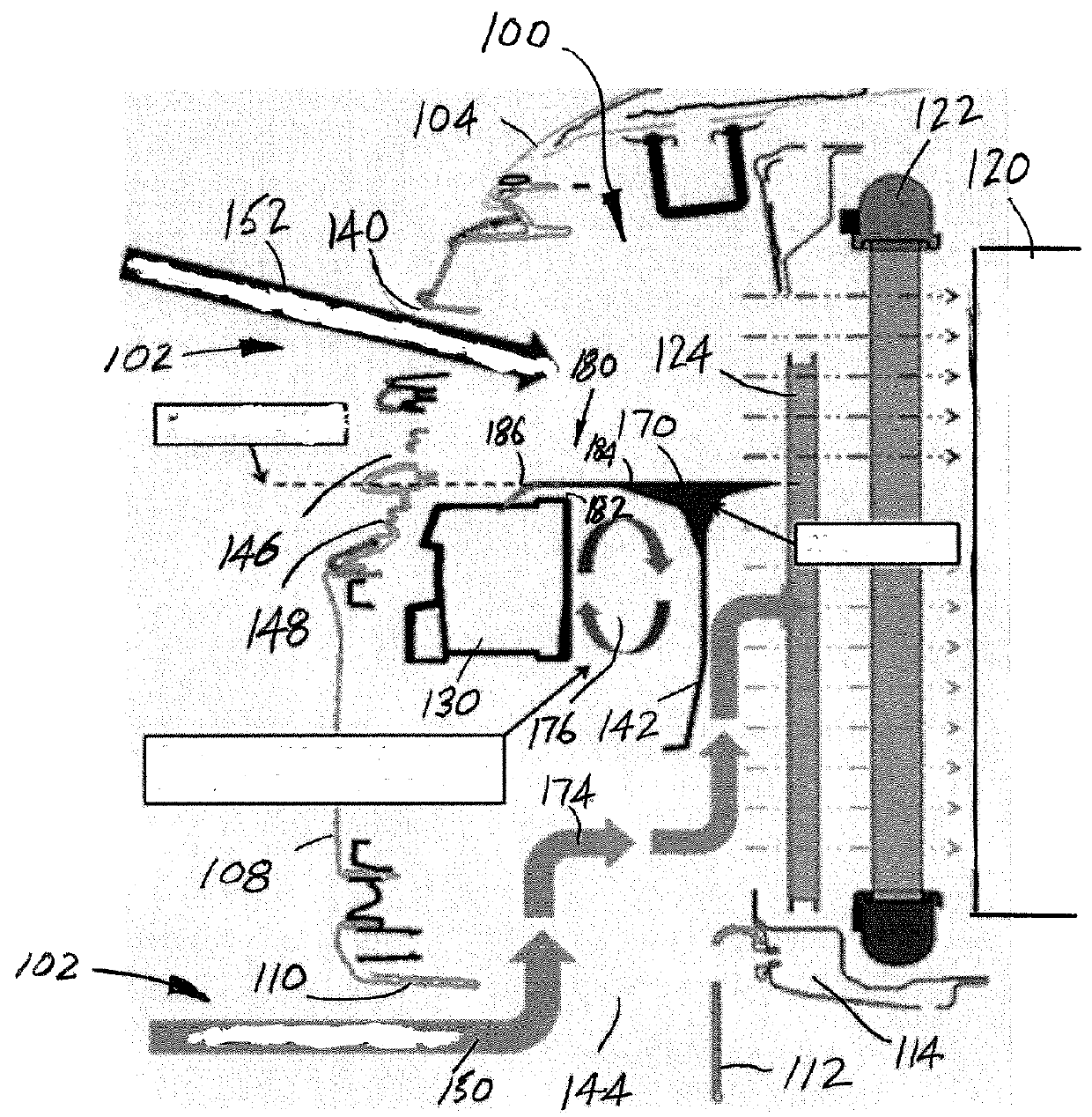
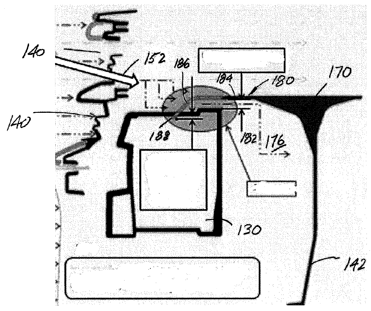
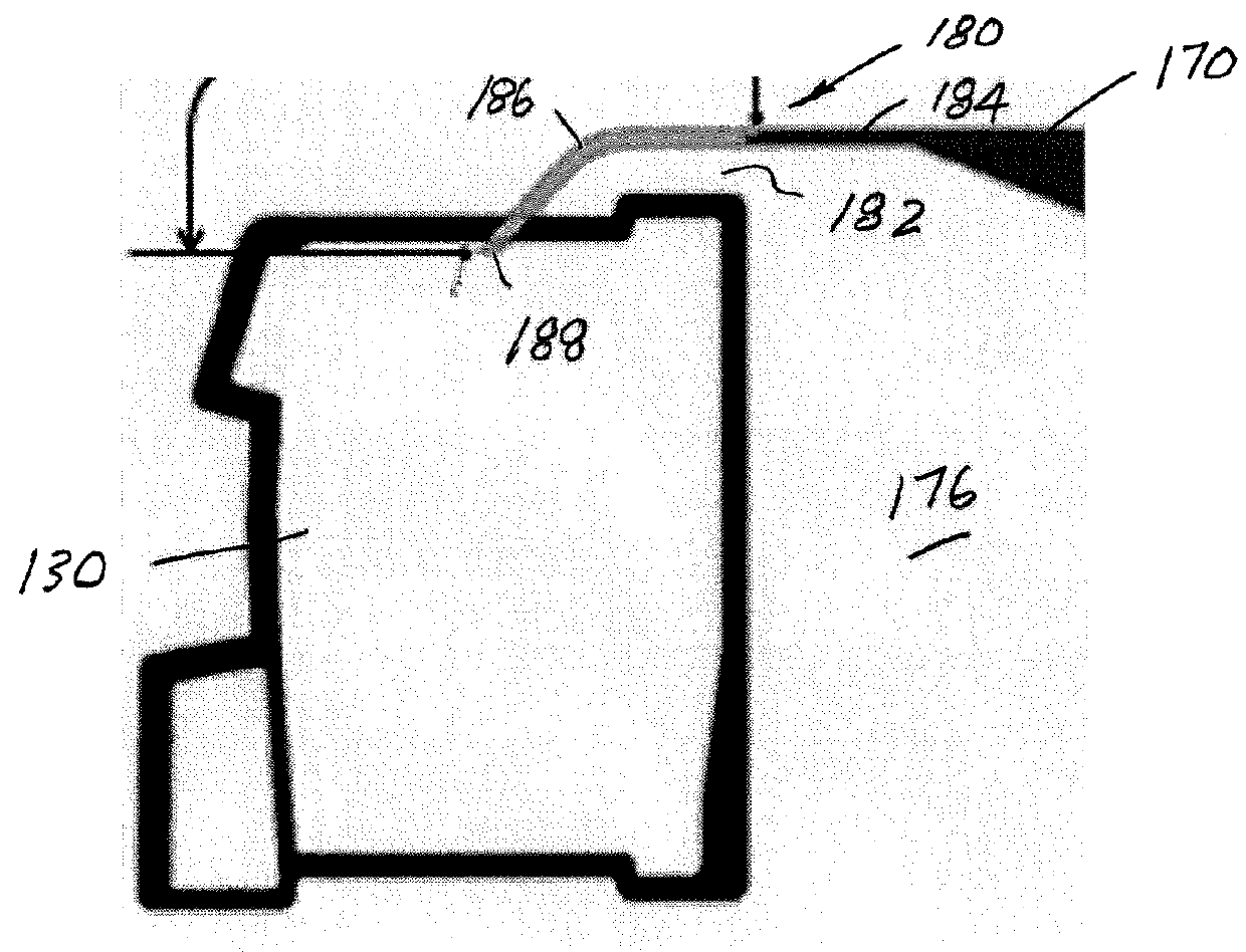
[0029]With reference to FIGS. 1-3, a vehicle engine compartment 100 is provided with an airflow introducing and directing system 102. The vehicle engine compartment 100 defines a substantially enclosed area which, as illustrated, is bounded at an upper end by a vehicle engine compartment upper surface 104, at a forward end by a vehicle engine compartment forward surface 108, at a first or left side by a first or left side surface (not shown), and likewise at a second or right side by a second or righ...


PUM

PropertyMeasurementUnit
Flow rateaaaaaaaaaa
Flexibilityaaaaaaaaaa

Abstract

An airflow directing assembly and associated method of assembling same, includes an air deflector having a first portion mounted in the vehicle engine compartment rearwardly of the bumper beam and including a separating wall that extends between and segregates a first, upper air flow path from a second, lower air flow path. The airflow directing assembly includes a second, flexible seal portion extending from the air deflector first portion in a direction toward the bumper beam. The flexible seal portion is configured for sliding, sealing engagement with a surface of a vehicle engine compartment component such as the bumper beam to accommodate build variation during vehicle assembly.

Description

BACKGROUND[0001]The present disclosure generally relates to an air-flow assembly for a vehicle engine compartment, and more particularly to an airflow directing member for a vehicle engine compartment that addresses inefficiencies and accommodates variations encountered during assembly of vehicles, as well as an associated method of forming an air separator assembly for an associated vehicle engine compartment. It is to be appreciated that the present exemplary embodiment is also amenable, however, to other like applications that encounter similar problems or require similar solutions.[0002]To facilitate cooling of a vehicle engine components, ram airflow is advantageously used during vehicle motion. More specifically, vehicle ram airflow openings may be positioned on the vehicle to receive an airflow that is directed toward and impacting the vehicle while the vehicle is in motion (ram airflow), and may introduce the ram airflow into the vehicle engine compartment. The ram airflow m...

Claims


Application Information

Patent Timeline
IPC IPC(8): B60K11/08F15D1/00
CPCF15D1/0005B60K11/08B60Y2410/123
Inventor KABBES, RYAN L.PEARSON, COLE CHARLESMIHOK, KYLE S.FARIA, STEVEISHIZONO, MANABU
Owner HONDA MOTOR CO LTD
Why Eureka
Try Eureka