V-shaped gearbox for driving turbomachine equipment

Active Publication Date: 2016-02-04
SN DETUDE & DE CONSTR DE MOTEURS DAVIATION S N E C M A
View PDF3 Cites 7 Cited by
  • Summary
  • Abstract
  • Description
  • Claims
  • Application Information

AI Technical Summary

Benefits of technology

[0015]The connecting rods are preferably oriented tangentially relative to the compressor casing. This allows the forces transmitted to the casing to be limited to tangential forces, and this limits the deformations of the casing.
[0016]The connecting rod

Problems solved by technology

In addition, there are a large number of surfaces of the gearbox (which extend in very different directions)

Method used


Image

  • V-shaped gearbox for driving turbomachine equipment
  • V-shaped gearbox for driving turbomachine equipment
  • V-shaped gearbox for driving turbomachine equipment

Examples


Example

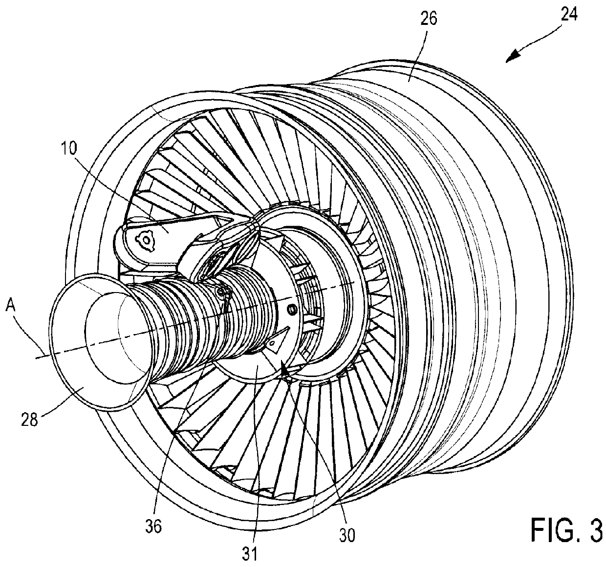
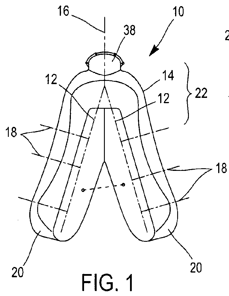
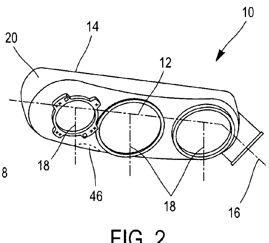
[0025]Reference is first made to FIGS. 1 and 2, which show a gearbox 10 for driving equipment (not shown) of a turbine engine, such as a turbojet engine or a turboprop engine of an aeroplane.

[0026]This gearbox 10 is intended to transmit mechanical power originating from the turbine engine by means of a radial shaft protruding therefrom, and to transmit said power to equipment such as pumps, electrical generators, etc. The transmission is carried out by a kinematic chain made up of successive gear units, said chain being made up of gear lines 12 which are located in non-parallel planes and are schematically shown by dashed lines in FIG. 1. A gear line 12 is a set of adjacent gear units which mesh with one another in principle and of which the toothed wheels are located in the same plane or in parallel planes; in other words, the rotational axes of the toothed wheels are all in parallel (perpendicular to this plane or to these parallel planes), and the toothed wheels which mesh direct...


PUM


Abstract

A gearbox for driving equipment of a turbomachine, including a substantially V-shaped box having two arms joined together by a joining part, the arms containing gear trains joined together at the joining part, and an attachment to the turbomachine. The attachment include a mechanism for insetting and/or for attaching the joining part and a suspension device of the arms.

Description

TECHNICAL FIELD[0001]The present invention relates to the attachment of a substantially V-shaped gearbox for driving turbine-engine equipment, such as a turbojet engine or a turboprop engine of an aeroplane.[0002]The applicant has developed a gearbox of which the casing is substantially V-shaped and comprises two arms which are interconnected by a joining part. The arms enclose gear lines which are located in non-parallel planes and are joined to each other by at least one gear unit which is located in the part joining the arms. The gearbox further comprises means for attachment to a casing of the turbine engine.[0003]Constructing the kinematic chain in a plurality of gear lines which are located in non-parallel planes makes it possible to arrange even a gearbox having large dimensions entirely in the proximity of the casing of the turbine engine, without too much space being taken up in the radial direction, the axial direction or in the angular direction, since the box is not rect...

Claims


Application Information

Patent Timeline
IPC IPC(8): F01D15/12F01D5/02F01D25/24F01D25/28F16H57/025F16H57/03
CPCF01D5/02F05D2220/30F05D2260/40311F05D2220/36F01D25/28F16H57/025F16H57/03F01D25/24F01D15/12F02C7/32F05D2250/38
Inventor BEUTIN, BRUNO ALBERTANCUTA, CARMENDEMOULIN, LAMBERT OLIVIER, MARIE
Owner SN DETUDE & DE CONSTR DE MOTEURS DAVIATION S N E C M A
Why Eureka
Try Eureka