
Assembled shield segment

A shield segment and assembled technology, which is applied to shaft equipment, shaft lining, tunnel lining, etc., can solve the problems of large transportation volume of shield segments, large amount of steel bars and concrete, waste of raw materials, etc., and simplify the installation steps. , The effect of improving the pressure resistance and improving the installation speed

Pending Publication Date: 2021-08-17
江雨
View PDF0 Cites 0 Cited by
  • Summary
  • Abstract
  • Description
  • Claims
  • Application Information

AI Technical Summary

Problems solved by technology

[0003] The shield segment is the main assembly component in shield construction, and is the outermost barrier of the tunnel. The bearer resists soil pressure, groundwater pressure and some special and existing functions. However, due to the creep of rock and soil materials and the Changes, construction disturbances, and some uncertain special factors will have deformation effects on the strata, and these factors cannot be completely determined within the length of the tunnel and the circumference of the tunnel. Therefore, the surrounding rock acts on different positions of the same shield segment The surrounding rock pressure is often different, and the surrounding rock pressure on the shield segment at different positions is often different, and the surrounding rock pressure will change uncertainly in different periods. Therefore, in order to ensure that the shield segment can meet the According to the needs of different locations, it has the ability to resist the change of surrounding rock. Those skilled in the art often make the shield segment very thick, and the amount of steel and concrete is large, which wastes raw materials to a large extent, and also makes the shield The transportation volume of structural segments is relatively large

Method used


Image

  • Assembled shield segment
  • Assembled shield segment
  • Assembled shield segment

Examples


Embodiment Construction

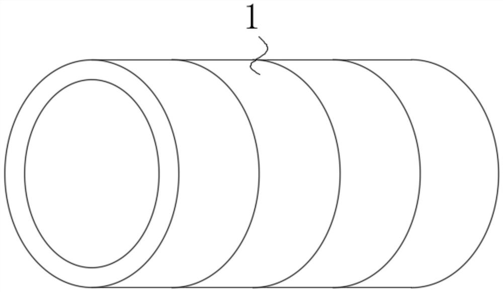
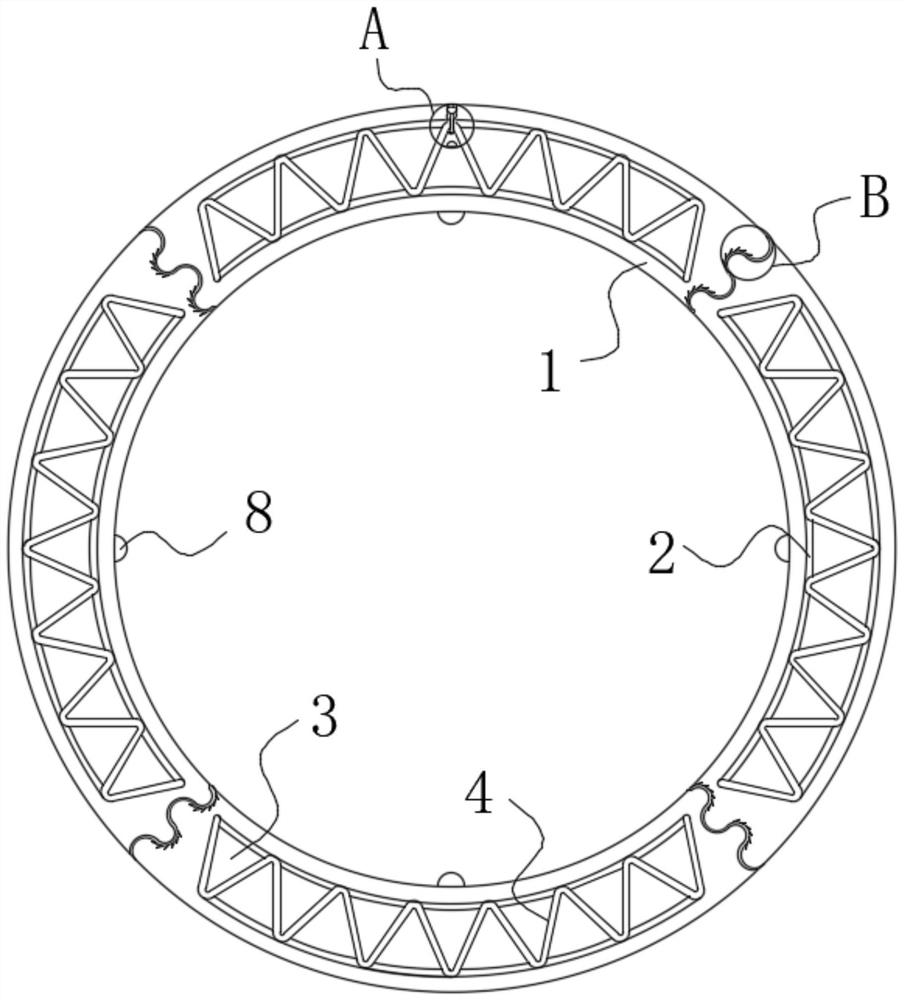
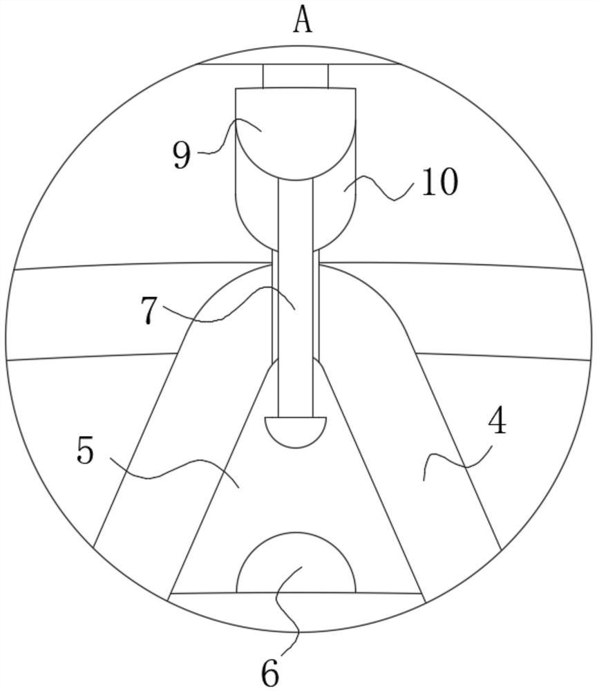
[0020] use Figure 1-Figure 4 An assembled shield segment according to an embodiment of the present invention is described as follows.

[0021] like Figure 1-Figure 4 As shown, an assembled shield segment according to the present invention includes a plug-in segment 1; the plug-in segment 1 is arranged in an arc shape, and the outer surfaces of both ends of the plug-in segment 1 are set in a wave shape, and the plug-in tube The wavy surfaces of the outer ends of the pieces 1 are assembled in a plug-in manner, and the plug-in tube pieces 1 form a ring shape after the plug-in is completed.

[0022] The inside of the plug-in tube piece 1 is fixedly equipped with a cladding plate 2; the cladding plate 2 is provided with two pieces in the plug-in tube piece 1, and the cladding plate 2 is arranged in an arc shape, and the cladding plate 2 is provided with A certain cavity is filled with flexible concrete 3 in the cavity between the cladding plates 2, wherein the flexible concrete...


PUM


Abstract

The invention belongs to the technical field of shields, and specifically relates to an assembled shield segment. The assembled shield segment comprises inserted-connection segment bodies, wherein the inserted-connection segment bodies are arranged in an arc shape, the outer surfaces of the two ends of each inserted-connection segment body are arranged to be in a wave shape, the inserted-connection segment bodies are assembled in an inserted-connection mode through the wave-shaped surfaces of the outer ends of the inserted-connection segment bodies, and a circular ring shape is formed after inserted-connection for the inserted-connection segment bodies is completed; after inserted-connection for the inserted-connection segment bodies is completed, a complete circular ring shape can be formed, and at the moment, under the limitation of wave-shaped grooves, the adjacent inserted-connection segment bodies are not prone to relative displacement, so that the overall structural strength of the segment is greatly improved, and meanwhile, the installing steps for the segment are simplified, so that the assembling speed for the segment is greatly increased, and the production efficiency is increased; and compared with screw connection in the prior art, the installation speed is greatly increased, and meanwhile, the structural strength of the segment can be greatly improved.

Description

technical field [0001] The invention belongs to the field of shield technology, in particular to an assembled shield segment. Background technique [0002] A shield machine is a tunnel boring machine that uses the shield method. The construction method of shield tunneling is the "shield" (referring to the supporting segment) of the tunnel constructed (laid) by the roadheader while excavating, which is different from the open construction method. Internationally, the generalized shield machine can also be used in rock formations, but it is different from the open (non-shield method) tunnel boring machine. In our country, it is customary to call the tunnel boring machine used in soft soil formations (narrow sense) shield machine, and the one used in rock formations is called (narrow sense) TBM. According to the working principle, the shield machine is generally divided into hand-excavated shield, extrusion shield, semi-mechanical shield (local air pressure, global air pressu...

Claims


Application Information

Patent Timeline
Patent Type & Authority Applications(China)
IPC IPC(8): E21D11/08E21D11/10
CPCE21D11/08E21D11/083E21D11/10
Inventor 江雨
Owner 江雨
Learn More