Brake apparatus

a technology of brakes and brakes, applied in mechanical devices, brake systems, transportation and packaging, etc., can solve problems such as uneven release operation, and achieve the effects of reducing braking force, reducing discomfort, and smooth brake release operation

Active Publication Date: 2016-02-04
HITACHI ASTEMO LTD
View PDF4 Cites 42 Cited by
  • Summary
  • Abstract
  • Description
  • Claims
  • Application Information

AI Technical Summary

Benefits of technology

[0006]The object of the present invention is to provide a brake apparatus that reduces discomfort felt at a time of brake release and achieves smooth brake release operation.
[0007]One aspect of the present invention is to provide a brake apparatus comprising: a piston configured to move a friction member to be pressed on a rotating member rotating with a wheel to apply braking force to a vehicle; an electric motor configured to operate a thrust retaining mechanism to thrust the piston and maintain braking force exerted by the thrust piston, in response to electric current applied to the electric motor; a command generator configured to generate an application command for applying braking force to the vehicle and a release command for releasing braking force from the vehicle; and a controller configured to operate the electric motor upon receiving the release command generated by the command generator, by performing current maintenance control which continuously applies electric current to the electric motor, and switching control which successively switches between a larger and a smaller amount of electric current applied to the electric motor, so as to reduce braking force exerted by the piston.

Problems solved by technology

The brake apparatus of Patent Document 1 can (gradually) decrease the rate of reduction in piston thrust when the slope of a road in a given direction is greater than or equal to a certain degree at a time of brake release than the rate when the road is level; however, the release operation may not be smooth.

Method used


Image

  • Brake apparatus
  • Brake apparatus
  • Brake apparatus

Examples


Embodiment Construction

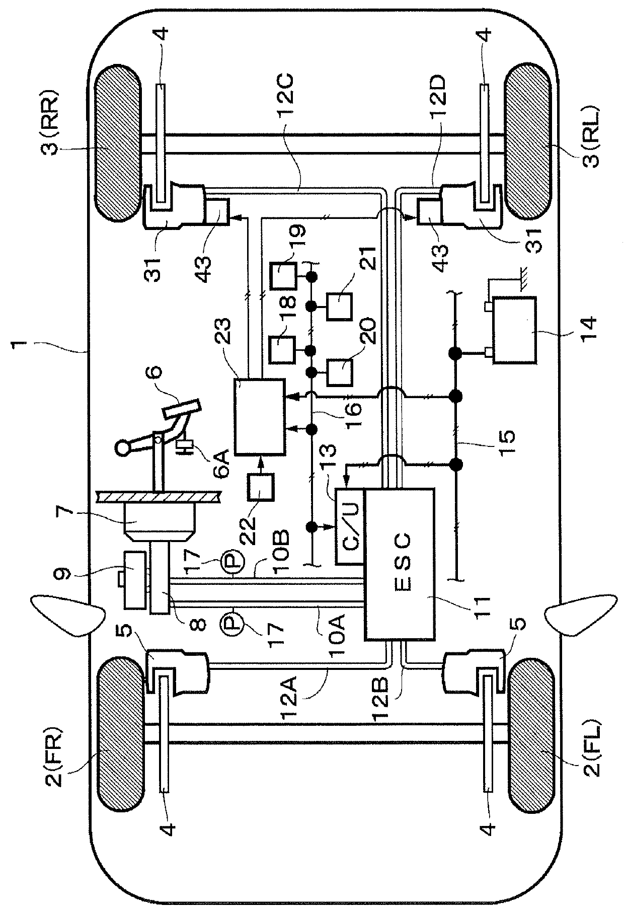
[0016]Below, embodiments of brake apparatuses are described with reference to the accompanying drawings, illustrating a brake apparatus mounted in a four-wheel vehicle as an example. In the flowchart of FIG. 6, “S” denotes a step (e.g., S1 for step 1).

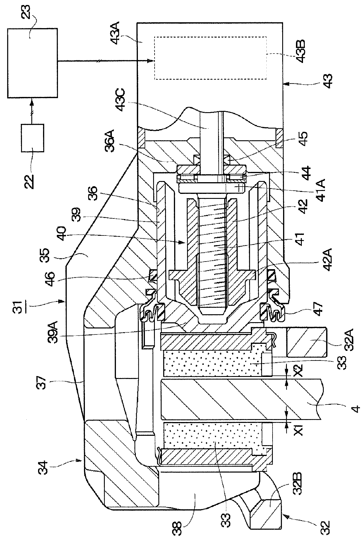
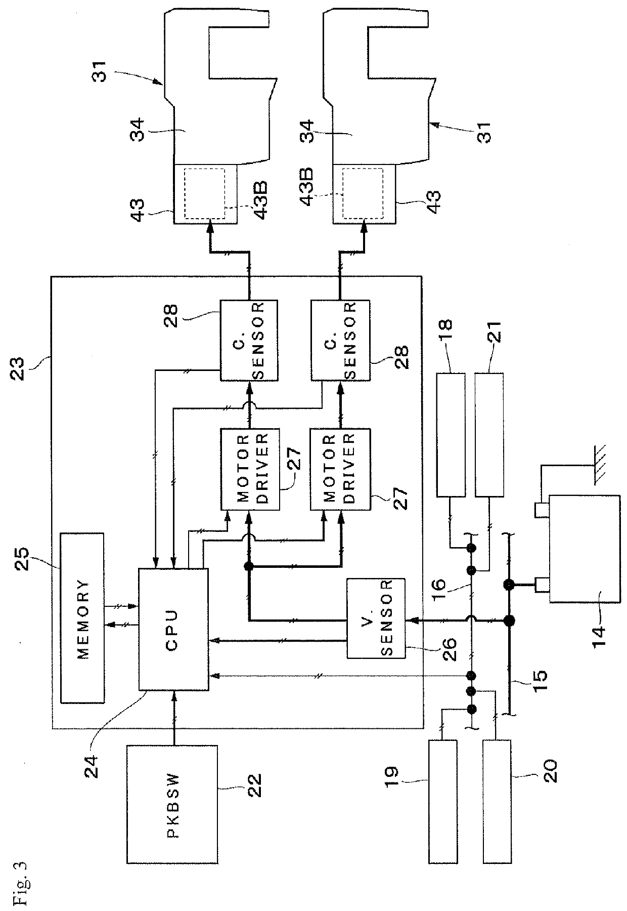
[0017]In FIG. 1, a vehicle body 1, which constitutes a body of a vehicle, has four wheels, i.e., left and right front wheels 2 (FL, FR) and left and right rear wheels 3 (RL and RR) on the bottom (road) side of the body 1. Each of the front wheels 2 and rear wheels 3 is provided with a disc rotor 4 serving as a rotor (rotating member) that rotates with the respective wheel (any one of the front and rear wheels 2 and 3). The disc rotors 4 for the front wheels 2 are each arranged for a hydraulic disc brake 5 with a part of the disc rotor being inserted in the hydraulic disc brake, and those for the rear wheels 3 each arranged for a hydraulic disc brake 31 with an electric parking brake function, a part of the disc rotor being inserted in ...


PUM


Abstract

A brake apparatus comprising: a caliper having a piston configured to move a brake pad to be pressed on a disc rotor rotating with a wheel; a thrust retaining mechanism located in the caliper to thrust the piston and maintain braking force exerted by the thrust piston; an electric motor mounted on the caliper to operate the thrust retaining mechanism; and a controller configured to apply electric current to the electric motor in response to an application command or a release command, thereby perform control according to the commands, wherein the controller, upon receiving a release command, configured to operate the electric motor to reduce braking force exerted by the piston by performing current maintenance control which continuously applies electric current to the electric motor and switching control which successively switches between a larger and a smaller amount of electric current applied to the electric motor.

Description

BACKGROUND ART[0001]The present invention relates a brake apparatus for applying braking force to a vehicle.[0002]Brake apparatuses having an electric parking brake function actuated by an electric motor are known for use in automobiles or other vehicles. To operate such a brake apparatus, the driver of a vehicle uses a parking brake switch to apply and release braking force with the aid of an electric motor of an electric parking brake. There is also a type of brake apparatus that automatically, without the driver's operation of the parking brake switch, applies braking force when a certain condition for brake application is met, for example, when the shift lever (or so-called select lever) is put into P (parking) or N (neutral), and releases it when a certain condition for release is met, for example, when the accelerator pedal is stepped on.[0003]Patent Document 1, listed below, discloses an electric parking brake apparatus that uses an electric motor at a lower duty ratio, e.g.,...

Claims


Application Information

Patent Timeline
Patent Type & Authority Applications(United States)
IPC IPC(8): F16D65/18F16D55/225
CPCF16D65/18F16D55/225F16D2055/0016F16D2121/04F16D2121/26B60T1/06B60T13/745F16D55/226F16D2121/24F16D2125/40
Inventor NISHINO, KIMIOMATSUBARA, KENICHIROYOKOYAMA, WATARUKOBUNE, TATSUROOIKAWA, HIROTAKA
Owner HITACHI ASTEMO LTD
Why Eureka
Try Eureka