Lighting system, track and lighting module therefore

a technology of lighting system and track, applied in the field of lighting system, can solve the problems of visual disturbance, difficult to attach the lamp to the track or move the module, and attract undesirable attention

Inactive Publication Date: 2016-02-04
SIGNIFY HLDG BV
View PDF9 Cites 79 Cited by
  • Summary
  • Abstract
  • Description
  • Claims
  • Application Information

AI Technical Summary

Benefits of technology

[0018]In particular, when the lighting module is provided with grooves that, in mounted position, grip around at least a part of a respective rail, for example as is present in a U-profile or L-profile of the rails, has the advantage that it is not removable from the rails and strips in a sidewise displacement, hence always keeps aligned with said strips. The module is only removable from the rails and strips by a si

Problems solved by technology

This results in a visually disturbed picture: a rail with lamps hanging underneath it all directed into different directions.
This attracts undesirable attention, as the focus of the customers should be on the products that are for sale.
Attaching the lamp to the track or moving the module is often difficult to do.
This lack of ease-of-use limits the shop owner or lighting designer to adjust the lighting on the fly as they see fit after the system has been installed.
This makes it difficult to light something on the ceiling as this will require the light to be redirected from a downwards direction into an upwards direction.
Furthermore, the strip itself will be in the light path, hampering a uniform or light projection on the ceiling.
Track based lighting systems having a pair of equidistant electric conductive (metallic) cables as rails for mounting of the lamps have the disadvantage that said cables itself are not rigid and thus have to be mounted with great tension to give them some rigidity rendering the installation of such lighting system relatively complex and cumbersome.
Furthermore, the tensioned, equidistant cables are still susceptible to vibrations and/o

Method used


Image

  • Lighting system, track and lighting module therefore
  • Lighting system, track and lighting module therefore
  • Lighting system, track and lighting module therefore

Examples


first embodiment

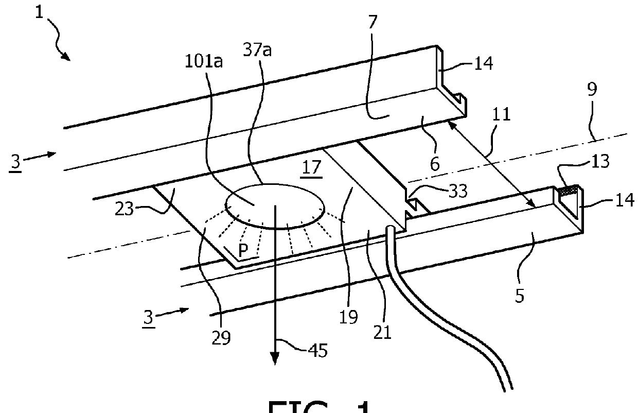
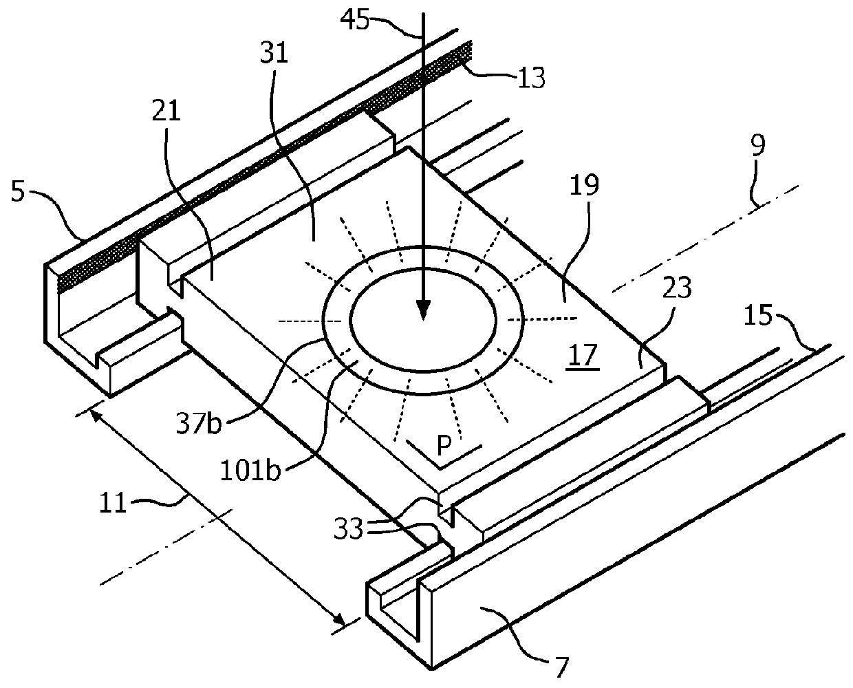
[0149]FIGS. 1 and 2 schematically show respectively a perspective bottom view and a top view of the lighting system 1 according to the invention. The lighting system comprises a track 3 comprising a first 5 and a second rail 7 extending mutually parallel along an axis or length axis 9. The first and second rail are spaced apart by an opening 11 lying in a plane P as defined by the parallel extending first and second rail.. If the first and second rail are slightly curved, i.e. that the first and second rail together bend slightly out of a flat plane upwards or downwards, then the plane P is considered locally and follows the curvature of the first and second rail. The first and second rails have a U-shaped profile in cross-section with two legs of the U-shaped profile extending in a direction perpendicular to plane P. Both the first and second rail comprise a respective conductive strip 13,15 which are isolated from each other and are provided at a respective rail wall 14 extending ...

second embodiment

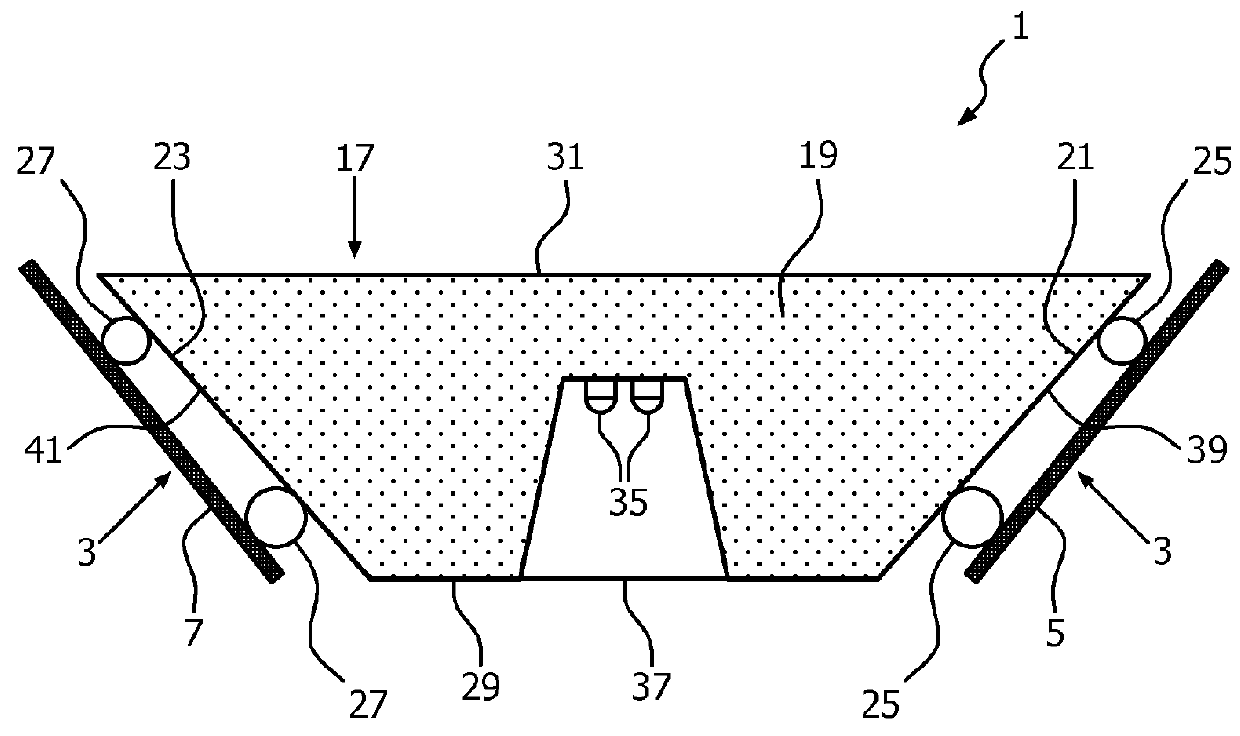
[0151]FIG. 4 shows a cross section of the lighting system 1 according to the invention. In this embodiment the lighting module 17 comprises a light source 35, in the figure two LEDs, in the base, which base 19 on its first side 29 has a light emission window 37 through which, during operation, light is issued to below the track 3. The lighting module at its first 21 and second end 23 has resilient contacts 25, 27 provided at a first 39 and second side face 41 extending from the first side 29 towards the second side 31 of the base and rests with these resilient contacts on the rails 5,7 of the wedge-shaped track 3.

third embodiment

[0152]FIG. 5 shows cross sections of the lighting system 1 according to the invention with the lighting module 17 being in a horizontal position and in a tilted position with respect to the plane P and opening 11. The side faces 39,41 of the lighting module are curved and are each provided with a metallic electric conducting coating 25,27 which act as electric contacts 25,27 of the module and which electrically connect to respective electric conductive strips 13,15 provided on the rails 5,7. The frictional contact between lighting module and rails enable the lighting module to stay in a somewhat tilted orientation (for aiming a light beam 43 issued at a tilting angle α with the direction of gravity through the light emission window 37). However, when the tilting angle becomes too large, i.e. that an end 21,23 of the lighting module becomes positioned too close to the bottom part of one of the rails, it will automatically slide back into a smaller, safer titling angle.

[0153]FIG. 6 sh...


PUM


Abstract

A lighting system comprising a track having a first and a second rail (5, 7), mutually extending equidistantly. Said first and second rail comprise a first respectively a second electrically conductive strip (13, 15), mutually electrically isolated. A lighting module comprising a first and second electrical contact, which lighting module in mounted position rests by gravitational force on the first and second rail. When mounted the first and second electrical contact are in electrical contact with a respective one of the first and second electrically conductive strip. The lighting module is dismountable from the track by a single displacement of the lighting module in a direction against the direction of the gravitational force.

Description

FIELD OF THE INVENTION[0001]The invention relates to a lighting system comprising a track and a lighting module. The invention further relates to a track and a lighting module.BACKGROUND OF THE INVENTION[0002]In retail and office environments it is common practice to use track-based systems to build the lighting system. These tracks can be suspended or recessed into the ceiling. To these tracks, lamps can be attached. Different types of these tracks are available. Some work with 230V but there are also lower voltage versions that enable different types of lamps to be used with the track. The track acts as a conductor of electricity and as a means to attach the lamps to. The lamps are usually mounted using some sort of clip. The main advantage of track-based systems is the flexibility it offers. It allows building an infrastructure of tracks which then allows lamps to be placed underneath the infrastructure of tracks built into that space.[0003]Within the domains of architecture and ...

Claims


Application Information

Patent Timeline
IPC IPC(8): F21V21/35F21S8/06F21V29/70
CPCF21S8/066F21V29/70F21V21/35F21W2131/405F21Y2101/02F21W2131/402F21S8/061F21S2/005F21V21/15F21V23/0457F21V23/0464F21V23/0471F21V23/06F21Y2105/00F21V23/045H01R25/147G02B6/0041G02B6/0083G02B6/0091H02G3/20G02B6/0011F21Y2113/00F21Y2103/10F21Y2115/10F21V2200/20
Inventor BERGMAN, ANTHONIE HENDRIKDEKKER, TIMKNAAPEN, BRAMVAN DEN BIGGELAAR, THEODORUS JOHANNES PETRUS
Owner SIGNIFY HLDG BV
Why Eureka
Try Eureka