
Lateral protecting mechanism and child safety seat therewith

Active Publication Date: 2016-02-11
BAMBINO PREZIOSO SWITZERLAND AG
View PDF5 Cites 30 Cited by
  • Summary
  • Abstract
  • Description
  • Claims
  • Application Information

AI Technical Summary

Benefits of technology

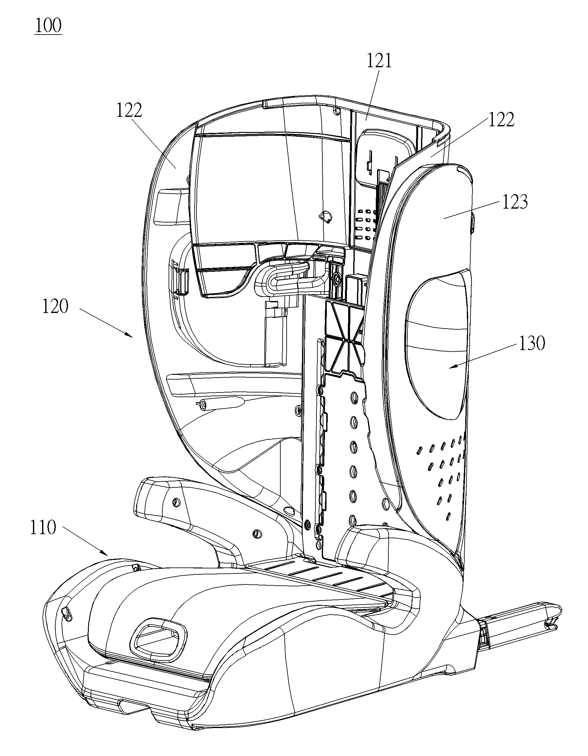
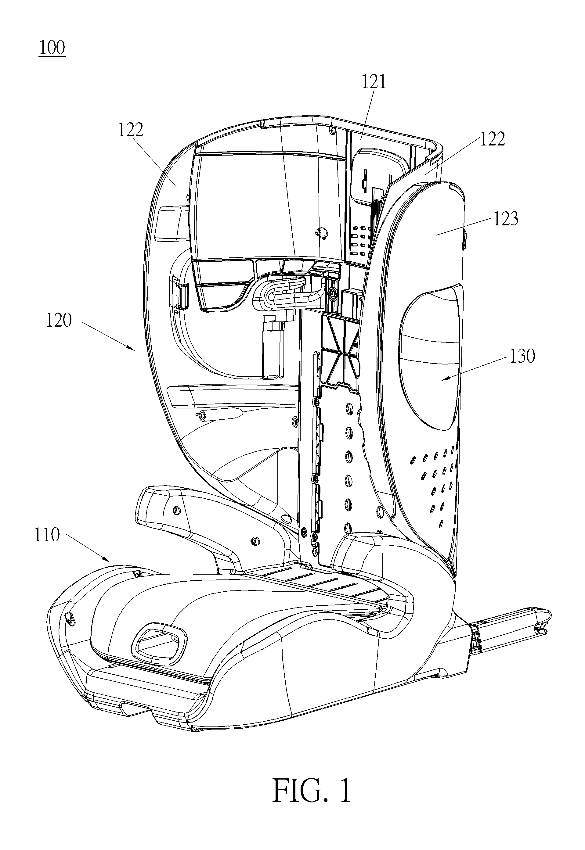
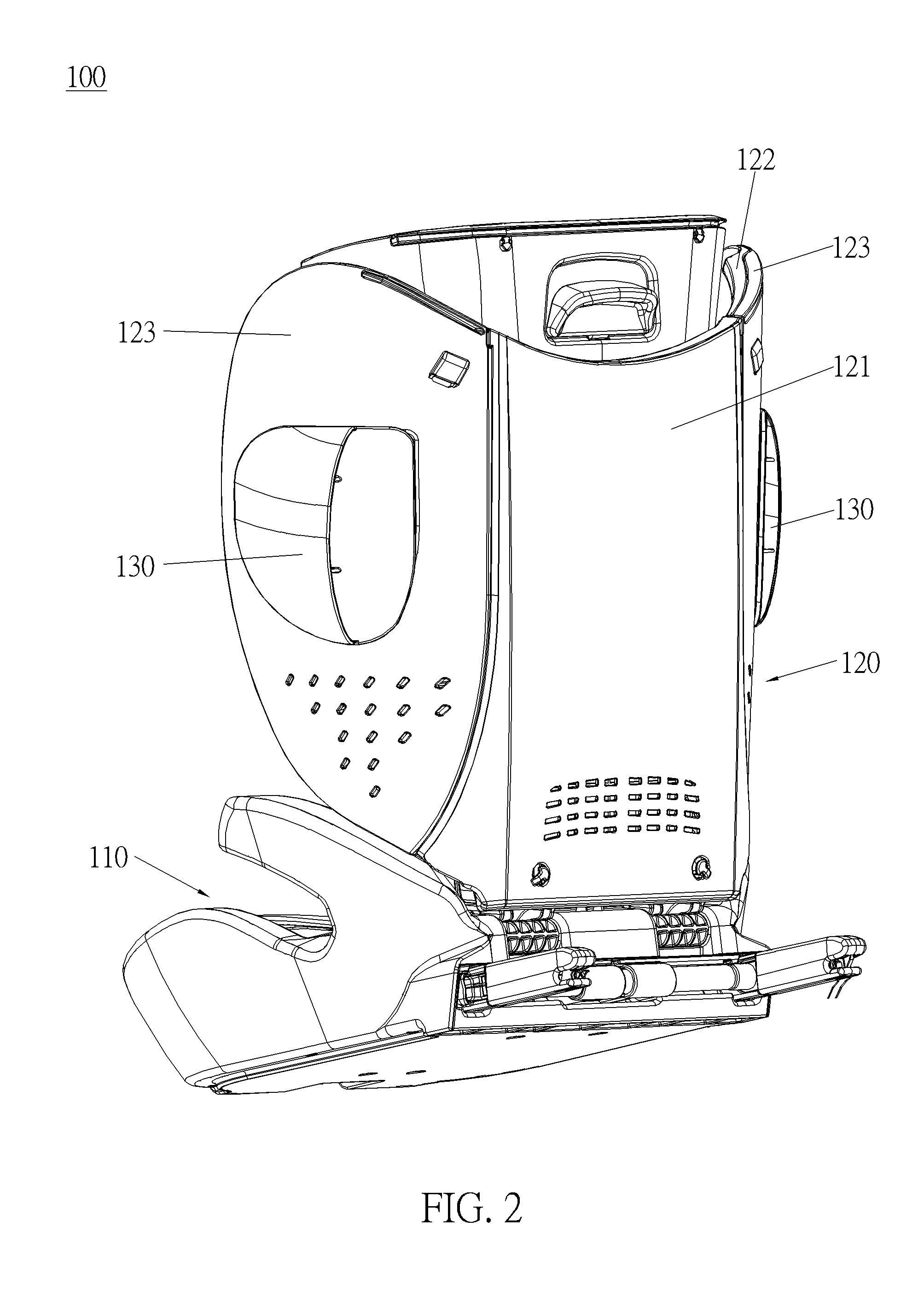
The present invention is a simple structure that provides a lateral protecting mechanism for a child safety seat. This mechanism is designed to effectively absorb a lateral impact in the event of a collision. The child safety seat has a protecting component located between the lateral swing and the lateral protecting block, which ensures the safety of the child.

Problems solved by technology

However, when a lateral collision occurs, a conventional child safety seat cannot provide an enough protecting effect for ensuring a child's safety because a lateral impact merely can be absorbed by lateral wings of the headrest and the backrest of the conventional child safety seat.

Method used


Image

  • Lateral protecting mechanism and child safety seat therewith
  • Lateral protecting mechanism and child safety seat therewith
  • Lateral protecting mechanism and child safety seat therewith

Examples


first embodiment

[0055]Please refer to FIG. 4 and FIG. 5. FIG. 5 is an enlarged diagram of an A portion of the child safety seat 100 shown in FIG. 4 according to the present invention. As shown in FIG. 4 and FIG. 5, two installing holes 1221 are formed on the two lateral wings 122 and corresponding to the two lateral protecting mechanisms 130. The two lateral protecting mechanisms 130 are respectively pivoted to the two lateral wings 122 and respectively received in the two installing holes 1221. Furthermore, the child safety seat 100 further includes two covers 123 respectively connected to two outer sides of the two lateral wings 122. Two through holes 1231 are respectively formed on the two covers 123 and corresponding to the two lateral protecting mechanisms 130, as shown in FIG. 4. The two through holes 1231 are also corresponding to the two installing holes 1221 on the two lateral wings 122 respectively. The lateral protecting mechanism 130 is pivoted to the lateral wing 122, such that the lat...

second embodiment

[0067]As shown in FIG. 13 to FIG. 15, in this embodiment, the cube 2320 of the lateral protecting mechanism 230 further includes a buffering rib 2325 protruding from a pressing portion 2322 for abutting against a cover 223. Specifically, the buffering rib 2325 is disposed along a longitudinal direction of the cube 2320 and cooperates with an edge of a through hole 2331 of the cover 223. In such a way, when a lateral impact happens on the lateral protecting block 231, the buffering rib 2325 is deformed by abutting against the edge of a through hole 2331 of the cover 223. Accordingly, a buffering effect for absorbing the lateral impact is provided by deformation of the buffering rib 2325, which ensures a child's safety. Other structures of the cube 2320 of the second embodiment are similar to the cube 1320 of the aforementioned embodiment.

[0068]Please refer to FIG. 16 to FIG. 23. FIG. 16 is a schematic diagram of a child safety seat 300 according to a third embodiment of the present i...


PUM


Abstract

A lateral protecting mechanism is disposed on a lateral wing of a child safety seat. The lateral protecting mechanism includes a lateral protecting block and a protecting component. An end of the lateral protecting block is pivoted to the lateral wing. The lateral protecting block is movable between a using position and a folding position. The protecting component is slidably disposed on the other end of the lateral protecting block. The protecting component protrudes from a side of the lateral protecting block and is located between the lateral wing and the lateral protecting block when the lateral protecting block rotates away from the lateral wing and is located at the using position, and the protecting component is received in the side of the lateral protecting block when the lateral protecting block rotates toward the lateral wing and is located at the folding position.

Description

BACKGROUND OF THE INVENTION[0001]1. Field of the Invention[0002]The present invention relates to a lateral protecting mechanism, and more particularly, to a lateral protecting mechanism with simple structure and effectively capable of absorbing a lateral impact, and a child safety seat therewith.[0003]2. Description of the Prior Art[0004]Child safety seats are designed for children with different weights or at different ages and are installed on cars for effectively ensuring children's safety. For example, when an emergency brake or a forward collision occurs, the child safety seat can absorb a forward impact on a child and prevent the child's body from moving forward rapidly, which avoids a second collision. When a backward collision occurs, a headrest and a backrest of the child safety seat can respectively support the child's head and body for preventing the child's neck from being injured due to swinging backward rapidly, which can reduce the child's injury and provides effects ...

Claims


Application Information

Patent Timeline
IPC IPC(8): B60N2/28
CPCB60N2/2872B60N2002/2896B60N2/2881B60N2/2884B60N2/2851B60N2/2887B60N2/4235B60N2/286B60N2/2869
Inventor ZHANG, DA, LIANG
Owner BAMBINO PREZIOSO SWITZERLAND AG
Learn More